
smps modeling
The design and analysis of Switch Mode Power Supplies (SMPS) necessitate a comprehensive understanding across various domains of electrical engineering. SMPS can be categorized into multiple topologies, each with distinct performance characteristics. Common types include Buck, Boost, Buck-Boost, Cuk, forward, and flyback converters, along with full-bridge, half-bridge, and ferro-resonant converters, as well as power factor correction converters. Each of these topologies has unique operational principles and applications, which are elaborated upon in the referenced literature.
Modern SMPS designs operate as feedback control systems, complicating the application of traditional stability analysis techniques. SPICE simulations typically focus on AC phase-gain characteristics derived from small-signal models around a DC operating point. However, the dynamic nature of switching transistors in SMPS, which frequently toggle between fully on and off states, presents significant challenges for stability analysis. High-frequency operation, often in the hundreds of kilohertz, requires that performance assessments consider feedback circuits and load filtering, which can have long time constants.
Achieving steady-state conditions in simulations can be time-consuming, particularly when step changes in load or other conditions necessitate lengthy intervals for re-evaluation. Additionally, the complexity of simulating PWM controller chips—often comprising thousands of transistors with digital states—can further exacerbate computational demands, leading to delays during transitions.
To effectively analyze SMPS designs and ensure stability, three primary methodologies are employed. The first is the classical exact method, which, while yielding precise insights into startup behavior, load responses, audio susceptibility, electromagnetic interference (EMI), and loss characteristics, does not facilitate stability assessment. The second method involves substituting the actual switching devices with idealized models, which simplifies analysis but still leaves stability concerns unaddressed. The third method employs an averaging technique during a switching cycle, allowing for the modeling of output effects during both the on and off states of the switch. This averaging results in a representation of the average operational behavior, enabling the establishment of an average operating point, which can subsequently be subjected to stability analysis. This methodology mirrors the behavior of an ideal transformer, where a variable duty-cycle input modulates a DC voltage, facilitating a more holistic understanding of the SMPS operation.SMPS design and analysis requires an understanding of many different areas of study. This article is intended to help the reader become familiar with the several different SMPS topologies, and their general performance characteristics. The major information is contained in the referenced articles. Dependent on who does the classification, several different switching converter types may be enumerated.
These may include the familiar Buck, Boost, Buck-Boost, Cuuk, forward converter and flyback converter. Also listed are full-bridge, half bridge, ferro-resonant converters, as well a power factor correction converters and perhaps even a few others!
The references provide descriptions and operational information on many of these circuits as well as the more familiar ones. It is expected that the interested person will have downloaded and read those documents and is familiar with the operation and characteristics of these converters.
Modern SMPS designs are feedback control systems. One might think at first that familiar stability analysis tools could be used; however this is not the case. The typical SPICE stability analysis centers about determination of the AC phase - gain characteristics.
However, SPICE calculates an AC small signal model about the DC operating point of a network. Where is the operating point of a switching transistor varying between hard on and hard off SMPS designs represent an extreme analysis problem. At one level, the converter is switching at frequencies reaching into the hundreds of kilohertz, however, its performance requirements are dependent on feedback shaping circuits and load filtering with long time constants.
Often much analysis time is required to reach the steady state conditions. Having reached these steady state conditions, if now the load is step changed, or other conditions occur, another long simulation interval is required. To this is the added problem of simulation of the PWM controller chips used with most SMPS designs. This could involve thousands of transistors and devices, many of which are operating as digital devices, creating numerous state changes, causing computations to slow at each transition.
Analysis can be extremely time consuming. To answer the analysis problem, as well as addressing stability of designs, a combination of three general methodologies are used. The first is the classical `exact` method. This model provided more exact information regarding circuit performance at start up, response to step loads and other changing load conditions, audio susceptibility, EMI, and losses at the cost of long computational times.
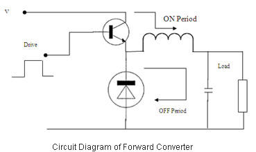
However stability cannot be examined in this method. A second method is to replace the transistor switch and/or the PWM controller chip with an idealized switching device. This offered many advantages; however, the problem of stability analysis remains. The third method involves averaging the effects during a switch cycle. As an example, for any topology we can model the effects on the output while the switch is `on` and while it is off, during a single switching cycle.
Now if these effects are time averaged, and the model produced instead of a switched waveform this average effect (or a signal which produced this average effect) then an `average` operating point could be determined and a stability analysis performed. This is in fact an `ideal transformer` application where a DC input voltage is transformed by a variable (duty-cycle) controlled transformer.
Now this presumes that the switching frequenc 🔗 External reference
Related Circuits
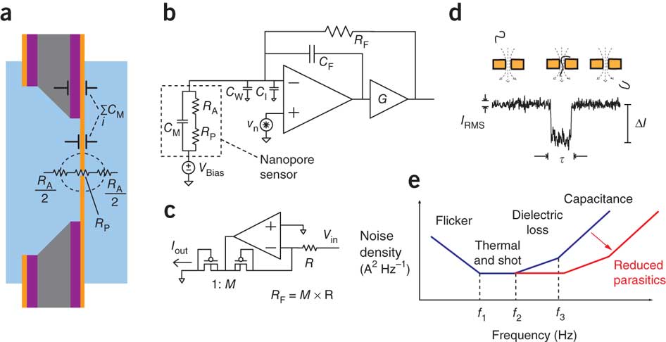
An illustration of the electronic impedances of a solid-state nanopore chip. A simplified circuit schematic of the voltage-clamp current preamplifier is provided. The circuit design of the low-noise current source substitutes for a feedback resistance (RF). An example transient...
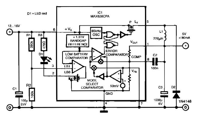
The circuit utilizes the MAX638CPA 5V CMOS Step Down Adjustable Switching Regulator IC, which converts an input voltage of 12 to 16 VDC into a stable 5VDC output. It requires only nine additional external components to complete the circuit....

When designing an offline boost-mode switching power supply, the objective was to model the power transformer to simulate inrush current and other startup behaviors. After conducting research and engaging in discussions on platforms like Google Groups and DIYAudio, as...
Switched mode power supply units (SMPSUs) are popular but difficult to build oneself as well problematic when it comes to understanding their design principles. Switched mode power supply units (SMPSUs) are widely utilized in various electronic applications due to their...
Switched Mode Power Supplies (SMPS) are categorized as DC to DC converters and DC to AC converters. Switched Mode Power Supplies (SMPS) are essential components in modern electronic devices, providing efficient power conversion from one form to another. The primary...
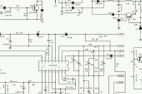
This document contains the datasheet and the circuit diagram of a PC Switching Power Supply utilizing the IC CG8010DX16. The CG8010DX16 is a highly integrated switching power supply controller designed for use in personal computer power supplies. It features a...