
Spice Component Circuit Modeling and Simulation

The offline boost-mode switching power supply design focuses on accurately modeling the power transformer to facilitate simulations of inrush current and startup characteristics. The LTSPICE simulation developed allows users to input basic physical measurements, which subsequently leads to automatic calculations of model parameters based on established equations. This capability is essential for engineers looking to analyze transformer behavior in various configurations, including single and dual winding setups.
The power supply is engineered to output +/-28VDC at a maximum current of 5 Amps, with additional +/-18VDC outputs tailored for operational amplifier circuits. The design is intended for compatibility with an AC mains transformer featuring dual secondary windings rated at 30V RMS. However, it can be adjusted to accommodate transformers with different secondary voltage ratings. The integration of adjustable linear regulators, such as the LT-1084, allows for flexibility in meeting specific application requirements.
To ensure minimal output ripple voltage, substantial capacitors are utilized on the adjust pins of the main regulators. The implementation of soft-start circuits is critical for protecting the regulators by controlling the input-to-output differential voltage during startup, thereby preventing potential damage.
The simulation also incorporates a star ground scheme that aids in understanding the implications of various ground conductor configurations. By including parasitic impedance elements, users can experiment with the effects of different PCB trace lengths and widths on overall performance. Furthermore, the simulation models parasitic effects, such as the equivalent series resistance (ESR) of capacitors, inductance, and leakage currents, as well as the resistance and inductance associated with PCB traces and wires.
Overall, this power supply design provides a robust and versatile solution for audio applications, while also serving as a valuable educational tool for understanding transformer modeling and power supply behavior in electronic circuits.When I was designing an off-line boost-mode switching power supply, I wanted to model the power transformer, to be able to also simulate the inrush current and other startup behavior. After doing some searches and asking some questions in discussion groups at Google Groups (Usenet message-traffic archive; a goldmine!) and DIYAudio, and downloading some technical
papers, including this excellent PDF about Modeling Transformers (PDF), I developed the LTSPICE simulation shown below. In the final version shown, only the simple physical measurements need to be entered (the portions inside the solid boxes), and the model parameters are then calculated automatically, using equations from the PDF referenced above.
This model should be valid for simple single primary / single secondary transformers, and also appears to be valid for dual primary / dual secondary transformers when both the primary windings and secondary windings are wired in parallel. To download the LTSpice ". ASC" file for the schematic above, Right-Click on the following link and then select "Save Target As".
Save the file WITHOUT the ". TXT" that`s at the end of the filename. This type of DC SERVO is meant to keep the DC offset voltage at the output of an amplifier at about zero volts. Typically, a DC Servo is used with an audio amplifier so that AC-coupling/DC-blocking capacitors can be omitted from the signal path.
(UPDATED, 23AUG07: REMOVED SIMULATED-WIRE-IMPEDANCE INDUCTORS FROM POWER SUPPLY LINES, TO AVOID NUMERICAL PROBLEMS WITH SPICE`S INTERNAL SOLVER. CHANGED TEST-LOAD`S RESISTANCE TO 8 OHMS FROM 50K. COMMENTED-OUT GMIN-CHANGING SPICE DIRECTIVE. ) To download the LTspice ". ASC" file for the schematic above, Right-Click on the following link and then select "Save Target As".
Then change the filename so you save the file _WITHOUT_ the ". TXT" that`s at the end of the filename. You should also download the LTspice ". PLT" file for the schematic above. Right-Click on the following link and then select "Save Target As". Then change the filename so you save the file _WITHOUT_ the ". TXT" that`s at the end of the filename. This power supply produces +/-28VDC at up to 5 Amps each, and also has +/-18VDC outputs for opamp-type circuitry. I originally designed this power supply for an audio power amplifier; a chipamp or gainclone type. It is designed to run from an AC mains transformer that has dual secondary windings of 30V RMS each, but could be modified to use other secondary voltages.
And other adjustable linear regulators could be used in place of the LT-1084 shown. With relatively large-value capacitors on the main 5-Amp regulators` adjust pins, this supply has very low output ripple voltage. But, to ensure that the main regulators` maximum input-to-output differential voltage specification is not exceeded during start-up, it was necessary to add the soft-start circuits.
A convenient star ground simulation scheme is used, including simple parasitic impedance elements, to make it easier for the user to begin to experiment with the sharing of various ground conductors by return currents, and to investigate the effects of different lengths and sizes of PCB traces or wires. This power supply simulation models many parasitic effects, including capacitors` ESR (Equivalent Series Resistance), inductance, and leakage current, and PCB traces` or wires` resistance and inductance.
There is nothing very novel or different about this PSU design, except perhaps that it uses simple MOSFET-based soft-start (inrush current limiter) circuits to enable the use of 🔗 External reference
Related Circuits

This circuit is a touch switch circuit, similar to a touch door alarm. It utilizes a 555 timer as the core component of the touch switch circuit. The operation begins when the plate is touched, triggering the 555 timer....
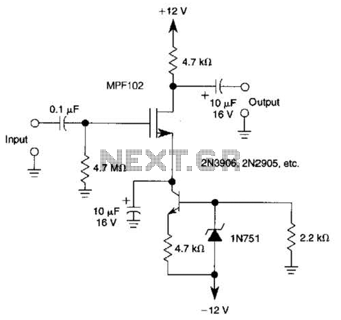
A current source (MPF102) in the source lead of the bipolar transistor 2N3906 allows for precise control of drain current. The circuit incorporates an MPF102 JFET configured as a current source, which is connected to the source terminal of a...
This infrared light valve has more parts, so it works better and more reliable for alarms. The circuit responds less ambient light. The light valve consists of a transmitter and a receiver. The transmitter consists of a NE 555...
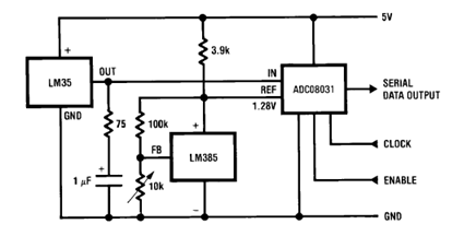
The circuit illustrates a Temperature to Digital Converter diagram utilizing the LM35 sensor, which includes a beneficial bypass capacitor connected from VIN to ground and a series RC damper. The described circuit employs the LM35 temperature sensor, a precision integrated...
The following circuit illustrates how to build a variable DC power supply circuit. This circuit is based on the 7805 IC. Features: other output is ... The variable DC power supply circuit utilizing the 7805 integrated circuit (IC) is designed...
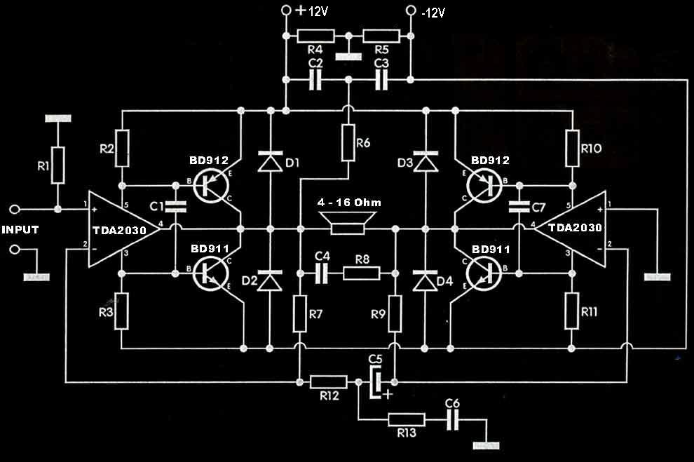
The TDA2030 amplifier circuit is suitable for driving low-frequency subwoofer speakers in home theater systems. The TDA2030 is a monolithic integrated circuit designed for use as a low-frequency class AB amplifier. This TDA2030 amplifier design requires a dual power...