
Inverting Power Supply Circuit

The circuit in question is designed to generate a negative DC voltage output from a positive DC voltage input. The operation is based on the principle of voltage inversion, typically achieved through the use of an operational amplifier (op-amp) in an inverting configuration or through specialized voltage inverter circuits.
At no load conditions, the output voltage closely mirrors the magnitude of the input voltage, providing a user-friendly interface for applications requiring a negative voltage reference. However, as the load increases, specifically at a 10 mA load, the output voltage decreases by approximately 3 V. This drop in voltage is an important consideration for applications that require stable output under varying load conditions.
The input voltage range is specified between +5 V and +15 V DC, which sets the operational limits for the circuit. It is crucial to adhere to this voltage range to avoid damaging sensitive components within the circuit, particularly the operational amplifier or any voltage regulator used. Exceeding the maximum input voltage of 15 V could lead to catastrophic failure, hence the need for protective measures such as voltage clamping or current limiting.
In practical implementations, additional components such as capacitors may be included to stabilize the output voltage and filter any noise present in the input signal. Diodes can also be utilized to prevent reverse voltage conditions that could damage the circuit. Proper thermal management should be considered, especially when the circuit operates near its maximum ratings, to ensure longevity and reliability.
Overall, this circuit serves a critical role in applications requiring a negative voltage supply, with careful attention to input limits and load conditions to ensure optimal performance and prevent damage. This circuit will provide a negative dc voltage that is approximately equal to the positive input voltage at no load and about 3 V less at 10 mA load. -`~ is from +5 to +15 Vdc. Do not exceed 15 V or Ul might be damaged.
Related Circuits
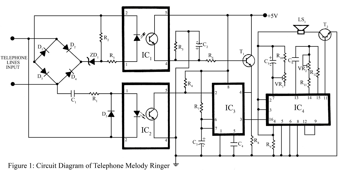
The telephone project described here is a telephone ringer that produces pleasant tunes when a call is received. The tunes generated by this telephone ringer are more melodious and soothing compared to those of traditional telephone instruments and piezo...

The Tesla Coil will utilize a high voltage (HV) power source that outputs 9 kV at approximately 30 mA. The construction of the Tesla coil includes six glass bottles, table salt, oil, and aluminum foil for the capacitors. The...
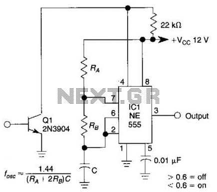
This gated 1-kHz oscillator provides press-to-turn-off functionality, along with waveforms available at the output of pin 3 and across capacitor C1. The gated 1-kHz oscillator circuit is designed to generate a square wave output at a frequency of 1 kHz....
All resistors have a tolerance of 5 or 10 percent and are rated for 1/4 watt. All capacitors have a tolerance of 10 percent and are rated for 35 volts or higher. This circuit effectively amplifies the output of...
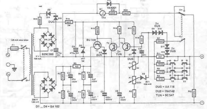
A DC power supply can be designed using high voltage transistors to provide an adjustable supply voltage ranging from 10 to 300 volts, which can be modified with potentiometer P1. Transformers used in these power supplies typically feature multiple...
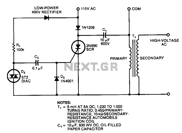
This circuit generates high-voltage pulses using an inexpensive auto ignition coil. By adding a rectifier to the output, the circuit produces high-voltage direct current (DC). The input to the circuit is 115 Vac. During the positive half cycle of...