
voltage regulator circuit with pass

The voltage regulator circuit described utilizes the LM317T as a primary regulator, which is a popular adjustable voltage regulator capable of providing a stable output voltage. The inclusion of a pass transistor allows for higher output currents by sharing the load, effectively increasing the current handling capability of the circuit. The series resistors play a critical role in determining the current sharing between the LM317T and the pass transistor, ensuring that the LM317T does not exceed its current limit.
The operation of the circuit can be further analyzed by considering the thermal management requirements. The heat generated by the LM317T and the pass transistor during operation must be dissipated effectively to prevent thermal shutdown or damage. A heat sink with adequate thermal conductivity and surface area is essential to maintain safe operating temperatures, especially under maximum load conditions where the heat dissipation can reach 23 watts.
The filter capacitor is crucial for smoothing the output voltage and reducing ripple. The calculation for the capacitor size using the formula C = IT/E is essential for ensuring that the output voltage remains stable under load conditions. The choice of a 36,000 µF capacitor reflects the need to maintain a ripple voltage below 1 volt, which is critical for sensitive electronic applications.
The power transformer must be selected based on the output voltage requirements and the additional headroom needed for the regulator to function correctly. Ensuring that the transformer provides at least 5.5 volts above the desired output voltage at full load is vital for maintaining regulation and performance.
In summary, this voltage regulator circuit design effectively combines the LM317T with a pass transistor to provide a robust solution for applications requiring higher output currents, while also emphasizing the importance of thermal management and component selection for reliable operation.This is a simple design for Voltage Regulator Circuit using pass transistor. The design has built by LM317T. The LM317T output current can be increased by using an additional power transistor to share a portion of the total current. The amount of current sharing is established with a resistor placed in series with the 317 input and a resistor plac
ed in series with the emitter of the pass transistor. The circuit is show in the figure below. In the figure, the pass transistor will start conducting when the LM317 current reaches about 1 amp, due to the voltage drop across the 0. 7 ohm resistor. Current limiting occurs at about 2 amps for the LM317 which will drop about 1. 4 volts across the 0. 7 ohm resistor and produce a 700 milli volt drop across the 0. 3 ohm emitter resistor. Thus the total current is limited to about 2+ (. 7/. 3) = 4. 3 amps. The input voltage will need to be about 5. 5 volts greater than the output at full load and heat dissipation at full load would be about 23 watts, so a fairly large heat sink may be needed for both the regulator and pass transistor.
The filter capacitor size can be approximated from C=IT/E where I is the current, T is the half cycle time (8. 33 mS at 60 Hertz), and E is the fall in voltage that will occur during one half cycle. To keep the ripple voltage below 1 volt at 4. 3 amps, a 36, 000 uF or greater filter capacitor is needed. The power transformer should be large enough so that the peak input voltage to the regulator remains 5.
5 volts above the output at full load, or 17. 5 volts for a 12 volt output. This allows for a 3 volt drop across the regulator, plus a 1. 5 volt drop across the series resistor (0. 7 ohm), and 1 volt of ripple produced by the filter capacitor. A larger filter capacitor will reduce the input requirements, but not much. 🔗 External reference
Related Circuits
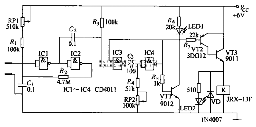
The automatic irrigation control circuit is designed to manage crop irrigation based on soil moisture levels. It is applicable in various agricultural settings, including state farms, orchards, vegetable greenhouses, and large farmland areas. The circuit comprises a soil moisture...

This servo system is designed to track the sun. Sunshine is focused onto a 50mm round image using an optical lens, and a 3DU33 photosensitive transistor is positioned at the light slit of AA' and BB'. It is essential...
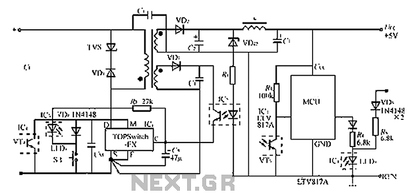
The circuit diagram of the TOPSwitch FZ chip switching power supply is controlled by microcontrollers (MCUs). The microcontroller can be utilized with inkjet printers, laser printers, and other computer peripherals. The TOPSwitch FX, which constitutes the switching power supply...
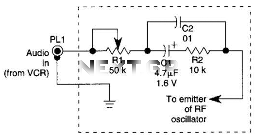
This continuous wave (CW) transmitter is capable of producing an output power of up to 3 watts. By applying a 24-volt supply to transistor Q2, the output power can be increased to as much as 10 watts. It is...
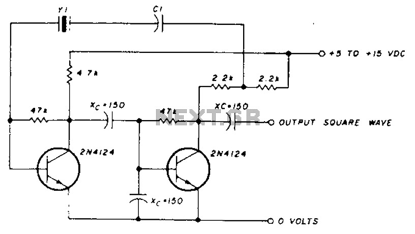
A transistor in series with capacitor C1 can be utilized to adjust the oscillator output frequency. The frequency may vary with changes in capacitance ranging from 20 pF to 0.01 µF, or as determined by the tuning capacitor. The...
The circuit illustrated in Figure 2-50 utilizes a field effect tube and a combination of electronic components to create a unique self-lighting controller. The working lamp remains illuminated at a reduced brightness rather than being completely turned off, which...
Warning: include(partials/cookie-banner.php): Failed to open stream: Permission denied in /var/www/html/nextgr/view-circuit.php on line 713
Warning: include(): Failed opening 'partials/cookie-banner.php' for inclusion (include_path='.:/usr/share/php') in /var/www/html/nextgr/view-circuit.php on line 713