
Remote-controlled fiber-optic Ceiling Light with Arduino
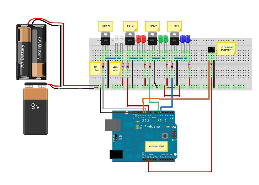
The circuit design employs an Arduino microcontroller to orchestrate the lighting effects of the LEDs. The use of four TIP122 transistors allows for efficient control of the high-brightness LEDs, ensuring that they can be driven adequately without exceeding their current ratings. Each transistor operates as a switch, enabling or disabling the flow of current to the respective LED based on the PWM signal received from the Arduino.
The configuration of the circuit includes a series connection of LEDs, which helps to maintain uniform brightness across the illuminators. The choice of a 470 Ω resistor in the power supply line is critical for current limiting, preventing excessive current from damaging the LEDs. The PWM control mechanism provides the ability to adjust the brightness of the LEDs dynamically, allowing for various lighting effects such as fading and color transitions.
The Arduino code provided includes functions for initializing the LEDs, receiving infrared signals, and controlling the fade effects of the LEDs. The use of a fade array allows for smooth transitions in brightness, enhancing the visual appeal of the lighting. The IR receiver component enables remote control of the lighting system, adding convenience and functionality to the design.
The overall schematic illustrates a well-organized and efficient control system for the LED illuminators, showcasing the integration of optical fibers with modern electronic components to achieve a sophisticated lighting solution. The design exemplifies the effective use of basic electronic principles combined with programming to create an interactive and visually engaging lighting system.A wood table with many holes with different diameters that house the optical fibers. The size of the ceiling lamp (90 cmx 60 cm) did not allow me to use a single bundle of fibers and this is the reason of the two beams I used, each of which comes with a LEDs illuminator as shown: The schematic with Arduino and its control circuit is shown in the figure above: it is a very simple circuit that I built on a breadboard. To control the high-brightness LEDs I used 4 transistors TIP122 whose base is driven with a PWM signal generated by Arduino. Each Arduino PWM output in connected to the each transistor base via a resistor of 1 kohm. The same type of LEDs are connected in series and hosted one in the first illuminator and the other in the second.
The line is connected to the positive external power supply via a 470 Ohm resistor. The transistor connected to the white LEDs is connected to pin 10 of Arduino, the TIP122 of the red LEDs to pin 9, the green LEDs to pin 6, that of the blue LEDs to pin 5. #include
enableIRIn(); // Start the receiver //Serial. begin(9600); } // Compare two tick values, returning 0 if newval is shorter, // 1 if newval is equal, and 2 if newval is longer // Use a tolerance of 20% int compare(unsigned int oldval, unsigned int newval) { if (newval < oldval *. 8) { return 0; } else if (oldval < newval *. 8) { return 2; } else { return 1; } } /* Converts the raw code values into a 32-bit hash code. * Hopefully this code is unique for each button. */ unsigned long decodeHash(decode_results *results) { unsigned long hash = FNV_BASIS_32; for (int i = 1; i+2 < results->rawlen; i+) { int value = compare(results->rawbuf[i], results->rawbuf[i+2]); // Add value into the hash hash = (hash * FNV_PRIME_32) value; } return hash; } void _initLeds() { for (int i=0; i<4; i+) { pinMode(pinLed[i], OUTPUT); analogWrite(pinLed[i], LOW); } } void _LedRGBOn() { for (int i=0; i<3; i+) { analogWrite(pinLed[i], 255); } } void ledFade(int ledpin, int time_wait) { for (int i=0; i<17; i+) { int j=16; analogWrite(ledpin, fade[j-i]); delay(time_wait); } delay(time_wait); for (int i=16; i>=0; i-) { int j=16; analogWrite(ledpin, fade[j-i]); delay(time_wait); } } void twoLedFade(int ledpin1, int ledpin2, int time_wait) { for (int i=0; i<17; i+) { int j=16; analogWrite(ledpin1, fade[j-i]); analogWrite(ledpin2, fade[i]); delay(time_wait); } delay(time_wait); for (int i=16; i>=0; i-) { int j=16; analogWrite(ledpin1, fade[j-i]); analogWrite(ledpin2, fade[i]); delay(time_wait); } } void threeLedFade(int ledpin1, int ledpin2, int ledpin3, int time_wait) { if ( _loop ) { for (int i=0; i<17; i+) { int j=16; analogWrite(ledpin1, fade[j-i]); analogWrite(ledpin2, 0); analogWrite(ledpin3, 0); delay(time_wait); } delay(time_wait); } for (int i=16; i>=0; i-) { int j=16; analogWrite(ledpin1, fade[j-i]
🔗 External reference
Related Circuits

A circuit that can automatically turn off the headlights or lamps of a vehicle after a preset time. This light switching circuit is constructed using a 555 timer integrated circuit (IC). The described circuit utilizes the 555 timer IC in...
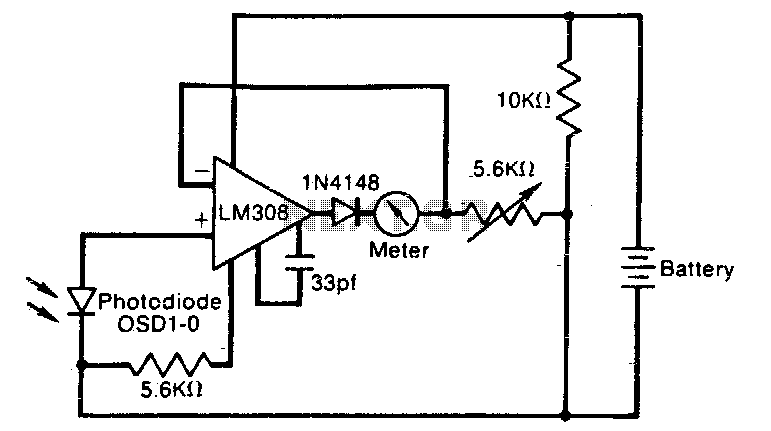
The meter reading is directly proportional to the logarithm of the input light power. The logarithmic circuit behavior arises from the nonlinear diode p-n junction current/voltage relationship. The diode in the amplifier output prevents the output voltage from becoming...

This document describes a family karaoke lighting design that employs various methods to control the circuit. The control circuit presented here features a four-way light output with loop jumping and speed control capabilities. The practical circuit utilizes a microphone...
The light is blinking instead of dimming. A specific software was used to illuminate the bulb without dimming, which includes the following code: ```cpp unsigned int i = 1; void setup() { Serial.begin(9600); ...
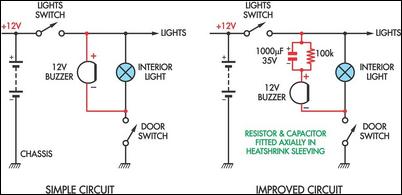
Two headlight reminder circuits are simple to install and operate based on the KISS (Keep It Simple Stupid) principle. The basic circuit consists of a 12V piezo buzzer connected between the lights circuit and a door switch. The buzzer...
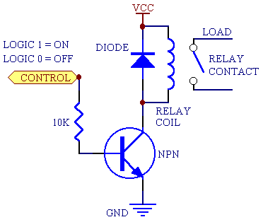
A 5V power supply is used to function as a switch controlled by an Arduino. Direct control from the Arduino pin is not feasible because most general-purpose relays require a minimum of 150mW to activate, which translates to over...