
solar tracker LM339 schematic
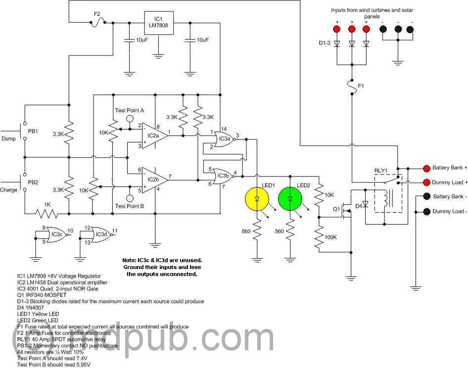
The LM339 circuit utilizes a dual LED arrangement to provide visual feedback regarding sensor readings. Each row of three LEDs is arranged to indicate different states or conditions based on the input from the sensor array. The west and east sensor LEDs serve to detect the direction of sunlight, facilitating the operation of a solar tracker system. The inclusion of a 1 MΩ resistor and a 10 nF ceramic capacitor in parallel with the sensor aids in filtering and stabilizing the sensor's output, ensuring accurate voltage levels are fed into the comparators.
The LM339, a quad comparator, is employed to compare the voltages from the sensor array against reference voltages set by the variable resistor R2. This resistor allows for fine-tuning of the sensitivity of the circuit, effectively creating a dead zone that prevents the motor from responding to minor fluctuations in light intensity. The outputs from the comparators are connected to a Darlington pair, which amplifies the current to drive the DC motor effectively. This arrangement allows for a robust control mechanism that can handle varying loads.
Powering the circuit with two series-connected batteries ensures that the LM339 operates within its specified voltage range. The use of two single-cell lithium-ion batteries or two 12-volt lead-acid batteries demonstrates the circuit's versatility and adaptability to different power sources. The center tap of the battery configuration provides a stable ground reference, crucial for the reliable operation of the comparators and the overall circuit.
This design exemplifies practical applications in solar tracking systems, with the collaboration of experienced engineers enhancing its reliability and functionality. The circuit's design and testing phases underscore the importance of community support in electronics, as facilitated by platforms such as the Electronics Tech Online Forum.The LED arrangement in the LM339 circuit below uses two rows of three LEDs with each LED connected in parallel, the two rows are connected in parallel but reversed polarity. The sensor array is made with three west LEDs and three east LEDs. A 1meg resistor and a 10n ceramic capacitor (103z) are also in parallel with the sensor. The sensor LEDs pro vide input voltage for two comparators on the LM339 chip with the variable resistor R2 providing a "dead zone" or sensitivity adjustment. Each comparator output is fed into a transistor Darlington pair which in turn drives the DC motor. The rail voltages are provided by two batteries connected in series with the center tap providing the ground reference.
We have tested this circuit with 2 single cell lithium-ion batteries providing +/- 4. 2 volts and two 12 volt lead batteries, the LM339 is rated for input voltages from +/- 2 volts to +/- 18 volts. This circuit is the result of the design efforts of Mike Mladejovsky, PhD EE. who helped us solve issues with the solar tracker #3 circuit via the Electronics Tech Online Forum which we highly recommend to anyone needing help understanding electronic circuits.
🔗 External reference
Related Circuits

This is a simple nickel-cadmium (NiCd) battery charger powered by solar cells. A solar cell panel or an array of solar cells can charge a battery at more than 80% efficiency, provided the available voltage exceeds the fully charged...
A current meter is employed to measure the current generated by a solar panel, exhibiting minimal power loss for currents within the 0-10A range. It also serves as a general-purpose DC current meter. The Gate Boost Solar Engine utilizes...

This document presents a diagram of a constant voltage/current power supply box. It is composed of three main components: spread current, constant voltage, and constant current. The design features two 3CF5 power transistors arranged in parallel, functioning as an...
This schematic illustrates a simple DIY solar cell phone or USB charger circuit. It is designed to charge any device that can be powered from a computer USB port, such as MP3 players, cell phones, and iPhones. The circuit...
The prototype was successfully assembled on a breadboard and subsequently built on a piece of Radio Shack protoboard for field use. The assembly process took only a couple of hours, and it functioned correctly on the first attempt. This...
This is an anti-theft alarm with wireless connectivity, referred to as the Anti-Theft Car Wireless Alarm. The FM radio-controlled anti-theft alarm can be utilized with any vehicle that operates on a 6 to 12-volt DC supply system. The mini...