
SK-IV with automatic voice-activated lights with music sounding circuit diagram
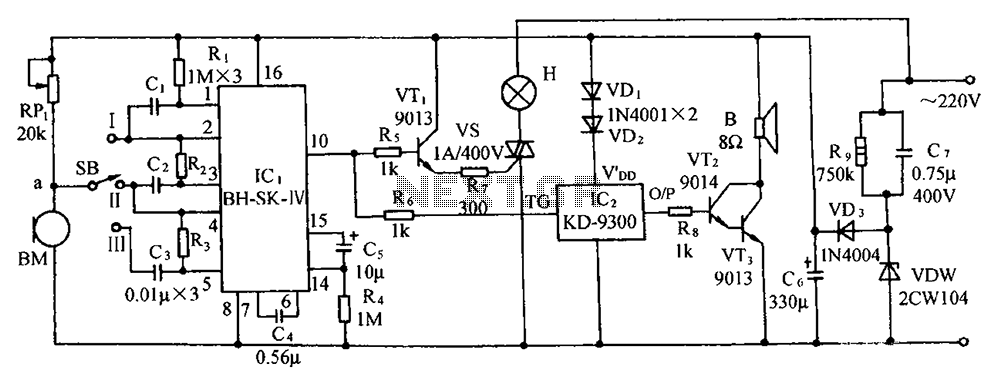
The described circuit is a complex assembly designed to process audio signals, primarily focusing on vocal input. At the heart of the system is the BH-SK-IV, which acts as the main processing unit. The microphone transducer captures sound waves, converting them into electrical signals that can be manipulated by the subsequent circuitry.
The voice circuits are responsible for amplifying and filtering the audio signals to enhance clarity and quality. This stage may involve various components such as operational amplifiers and passive filters that work together to ensure that the output is suitable for further processing.
An SCR (Silicon Controlled Rectifier) control circuit is integrated into the design to manage power flow within the system. This component allows for precise control of the electrical supply to the vocal music buck rectifier circuit, which is essential for converting the AC input into a usable DC output. The buck rectifier circuit is particularly important for reducing voltage levels while maintaining power efficiency, ensuring that the audio processing components receive the appropriate voltage levels.
The AC circuit serves as the power supply backbone for the entire system, providing the necessary energy for operation. It is designed to handle the input power requirements safely and efficiently, often incorporating transformers and rectifiers to convert high voltage AC to lower voltage levels suitable for the rest of the circuit.
Overall, this circuit is a sophisticated assembly that harmonizes various electronic components to achieve effective vocal signal processing, making it suitable for applications in audio equipment, communication devices, and other electronic systems requiring sound input and processing. Circuit as shown, including microphone transducer, voice circuits, SCR control circuit, vocal music buck rectifier circuit and the AC circuit. BH-SK-IV is the core of the devic e circuit.
Related Circuits
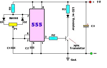
A user is new to the forum and has limited experience in DIY electronics. The current project involves creating a battery-powered LED dimmer circuit. The objective of the project is to design a battery-operated LED dimmer circuit that allows for...
Generating long delays of several hours can be achieved using a low-frequency oscillator and a binary counter. A single Schmitt Trigger inverter stage (1/6 of 74HC14) functions as a square wave oscillator, producing a low frequency of approximately 0.5...
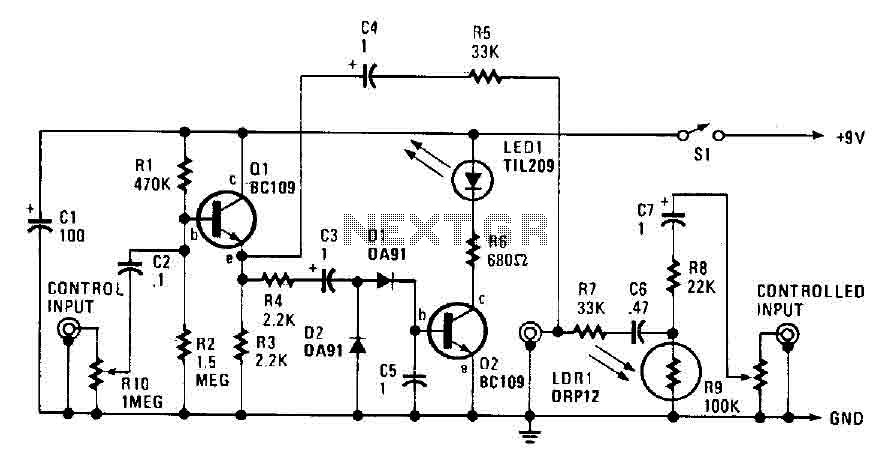
The automatic fader reduces the background music level when narration is in progress. The control input through RIO, a preset audio level control, is directed into an emitter-follower buffer stage (Q1). This buffer provides high input impedance and ensures...
The bicore is the basis of advanced BEAM. Most intermediate to advanced BEAM robots are built off of the bicore. Uses go all the way from photovores to servo motor drivers to walkers. What it is is basically just...
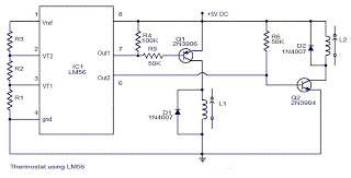
The values of the LM56 thermostat project circuit diagram for resistors R1, R2, and R3 at the travel points VT1 and VT2 can be determined using the following equations. This electronic circuit thermostat with the IC LM56 serves as...
This is an efficient four-stage stabilized power supply unit designed for testing electronic circuits. It delivers well-regulated and stabilized outputs, which are crucial for achieving accurate results in most electronic applications. The circuit features an audio-visual indication system that...