
FM IF MW radio receiver circuit using LA1260 IC
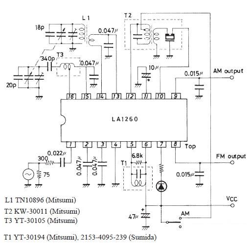
The LA1260 integrated circuit (IC) is specifically designed for use in FM and AM radio applications, making it a versatile choice for radio receiver projects. The circuit typically includes essential components such as resistors, capacitors, and inductors to support the operation of the IC. The LA1260 features built-in functions including a low-noise amplifier, mixer, and demodulator, which simplifies the design process and reduces the need for additional external components.
The schematic diagram of the FM IF MW radio receiver circuit will generally depict the LA1260 connected to an antenna for signal reception. The antenna captures radio frequency signals, which are then fed into the input of the LA1260. The IC processes these signals, amplifying and demodulating them to extract the audio information.
Power supply requirements for the LA1260 are typically in the range of 5 to 12 volts, depending on the specific configuration and the desired performance characteristics. Bypass capacitors are often included to stabilize the power supply and reduce noise, ensuring optimal operation of the IC.
Output from the LA1260 can be connected to an audio amplifier or directly to a speaker, allowing the demodulated audio signal to be heard. Additional features such as volume control and tone adjustment can be implemented using potentiometers and additional circuitry, enhancing the overall user experience.
In summary, the LA1260 IC serves as a central component in a simple FM IF MW radio receiver circuit, integrating multiple functions to facilitate efficient radio signal processing. This design is suitable for hobbyists and engineers looking to create AM and FM radio projects with minimal external components.A very simple FM IF MW radio receiver circuit can be designed using the LA1260 IC manufactured by Sanyo Semiconductor . As you can see in this FM IF MW radio receiver circuit schematic the LA1260 ic can be used in AM FM radio receiver electronic projects .LA1260 has integrated in the package many functions.
🔗 External reference
Related Circuits
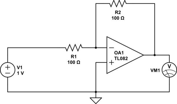
Considering a simple circuit as illustrated below, when the voltage source activates suddenly (changing from 0V to 1V), current will flow through the resistor R1. Assuming an ideal operational amplifier (op-amp) that draws no current, and an ideal voltmeter...
In addition to its primary function as a headphone amplifier, this circuit is applicable in various scenarios requiring a wide bandwidth low power amplifier. It utilizes an operational amplifier (op-amp) with its output current enhanced by a pair of...
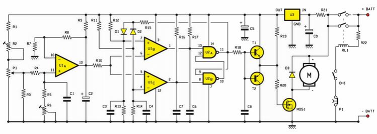
An electric scooter and E-Bike PWM speed controller circuit has been constructed. However, the oscillator is not functioning as intended. The printed circuit board has been checked and is confirmed to be in good condition, including all resistors. The electric...
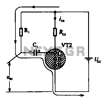
When VRI is off, 0 [2 is activated, allowing current to flow through RJ and Ci. When VT1 conducts, charging of C1 begins, causing it to discharge. This results in an inverting charge on C1, making the voltage positive,...
This circuit utilizes a PIC microcontroller and an internal 1 kHz sinewave table to generate an accurate sinewave. It requires only a few external components for filtering. The sinewave benefits from high frequency accuracy due to its generation from...
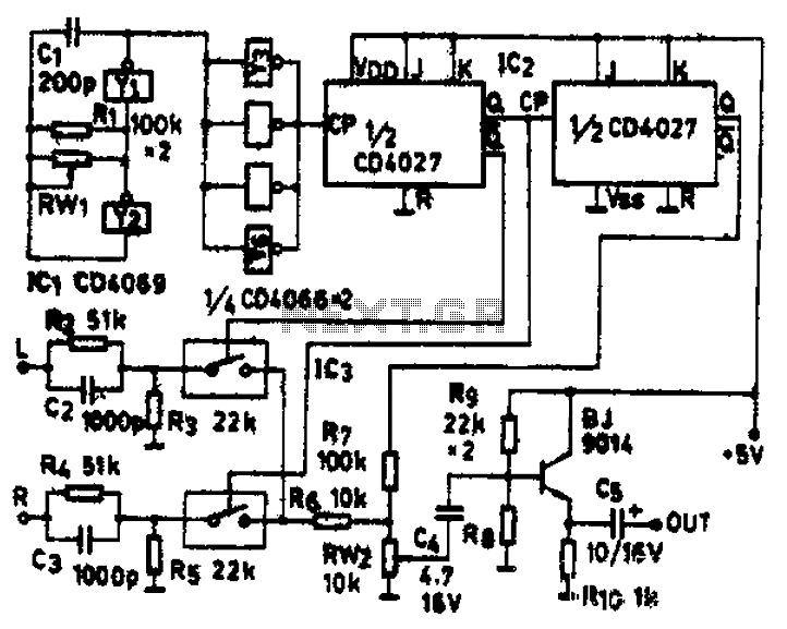
The circuit schematic diagram features IC1 (4069) and components Y1 and Y2, which together form a frequency oscillator operating at 76 kHz. Components Y3 to Y6 provide isolation and shape the output into the IC2 (CD4027) dual JK flip-flop,...