
Solar Tracking Circuit
The solar tracking circuit utilizes a combination of photovoltaic (PV) cells, sensors, and a microcontroller to adjust the orientation of solar panels in real-time, ensuring they are always positioned to capture the maximum amount of sunlight. The key components of the circuit include light-dependent resistors (LDRs) that detect the intensity of sunlight on different sides of the panel. These sensors provide feedback to the microcontroller, which processes the data and actuates motors to tilt or rotate the solar panels accordingly.
The circuit typically features a dual-axis tracking mechanism, allowing the solar panels to move both horizontally and vertically. This is achieved through the use of servo motors or stepper motors, which are controlled by the microcontroller based on the input from the LDRs. The design also incorporates a power management system that regulates the output voltage and current generated by the solar panels, ensuring it is suitable for charging batteries or powering electronic devices.
In addition to the core components, the circuit may include protection features such as diodes to prevent reverse current flow, capacitors for smoothing the output, and voltage regulators to maintain stable output levels. The overall efficiency of the solar tracking circuit is significantly enhanced compared to fixed solar panels, as it maximizes energy capture throughout the day, adapting to the sun's trajectory.
This solar tracking circuit represents an effective solution for renewable energy generation, contributing to sustainable practices by optimizing the use of solar energy.Here is solar tracking circuit. This circuit is a power generating method from sunlight. This circuit need only maximum sunlight to generate power. This project. 🔗 External reference
Related Circuits
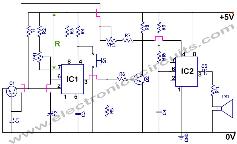
555 Timer with Audio Alarm Circuit. This circuit serves as a straightforward electronic timer equipped with an audio alarm feature. The 555 timer is a versatile integrated circuit widely used in various timer, delay, pulse generation, and oscillator applications. In...
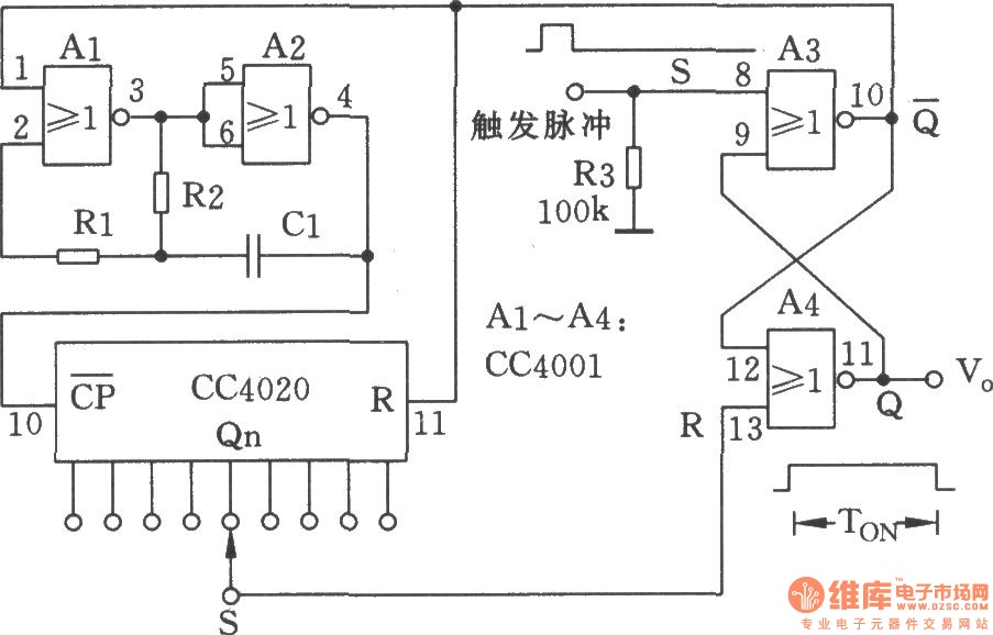
The NC monostable multivibrator circuit depicted in the chart consists of four 2-input NOR gates (CC4001) and a 14-bit binary serial counter/divider (CC4020). It is primarily utilized as a time delay switch or timer in automatic control equipment. The NC...
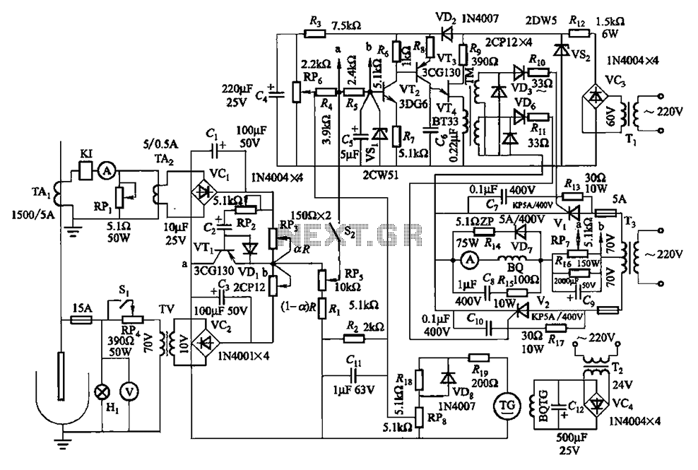
The circuit is illustrated in Figures 16-95 to 16-97. The electrode automatic adjuster demonstrates enhanced performance, featuring a high-accuracy, well-linear current output type bridge. Additionally, it incorporates a differential arc current negative feedback circuit (advanced) that allows for preemptive...
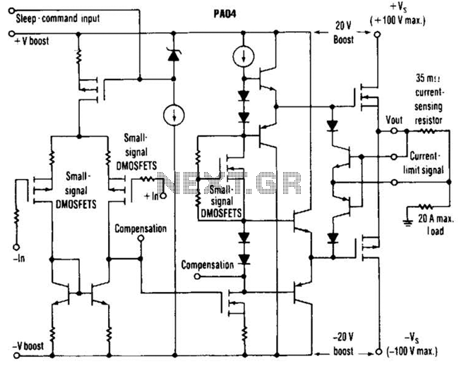
This circuit from Apex Microtechnology can deliver 180 V peak-to-peak at 90 kHz into a 4-ohm load. The PA04 can deliver 400 watts RMS into an 8-ohm load with low total harmonic distortion at frequencies exceeding 20 kHz. The circuit...
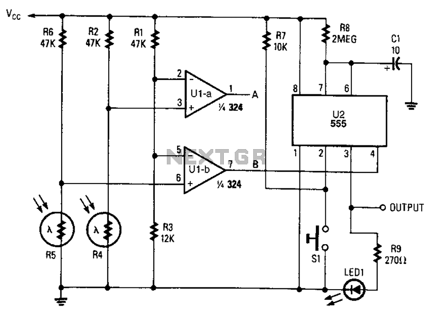
A combined monostable multivibrator using the 555 timer integrated circuit, along with a pair of light control comparators. This circuit can be utilized to control a load based on the timing parameters set within the circuit. The circuit comprises a...
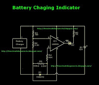
This is a battery charger indicator circuit diagram. When the battery is charging, it is indicated by an LED. This circuit can be used with a 12V battery with a charging current of less than 1A. The battery charger indicator...