
NC monostable multivibrator circuit
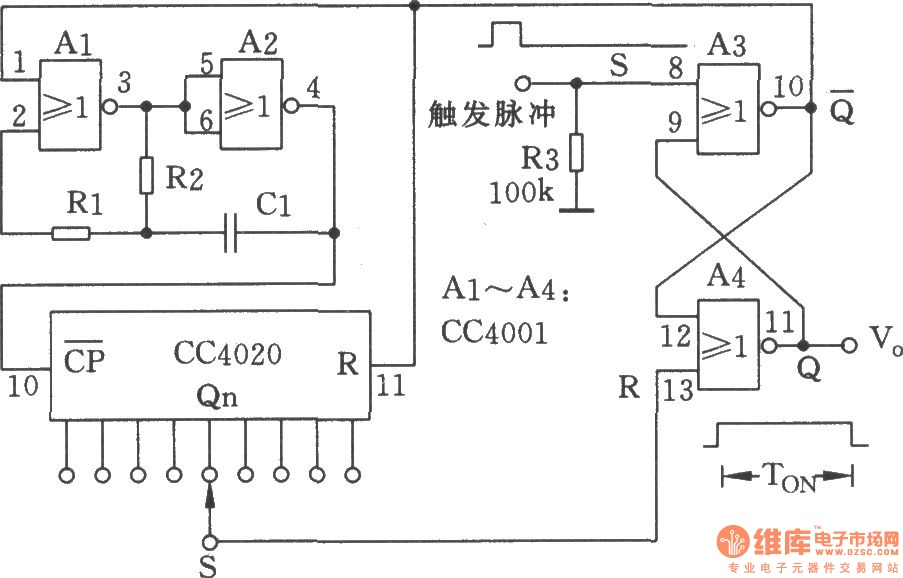
The NC monostable multivibrator circuit is designed to provide a single output pulse in response to an input trigger. The circuit's operation is based on the characteristics of the NOR gates and the binary counter. The four 2-input NOR gates (CC4001) are configured to achieve the necessary logic functions that enable the monostable operation. When a trigger signal is applied, the NOR gates generate a high output for a predetermined duration, dictated by the timing components connected to the circuit.
The timing aspect is managed by the 14-bit binary serial counter/divider (CC4020), which counts the clock pulses generated by an external oscillator or timing circuit. The output pulse width can be adjusted by varying the resistor and capacitor values associated with the timing components. This flexibility allows for precise control over the timing interval, making the circuit suitable for various applications in automatic control systems, such as delay switches, timers, or pulse generators.
In practical applications, the monostable multivibrator can be employed in scenarios where a temporary action is required following a specific event, such as turning on a device for a set amount of time after a button press. The incorporation of the CC4020 allows for scalability in timing intervals, enabling a wide range of operational conditions to be met. Proper implementation of this circuit can enhance the functionality and reliability of automated systems.The NC monostable multivibrator circuit shown in the chart is composed of four 2 input NOR gate CC4001 and 14-bit binary serial counter / divider CC4020. It mainly used as time delay switch or timer in automatic control equipments.. 🔗 External reference
Related Circuits
This article discusses several opamp-based headphone amplifier circuits, including suggestions for selecting opamps, input coupling and filtering, high current output stages and power supply options. There are no recommendations for specific opamp brands or models. For tube devotees, there...

Power Amplifier Speaker Protection Circuit Schematic. When a power amplifier is switched on, a loud thump sound is often heard due to a sudden heavy discharge. The power amplifier speaker protection circuit is designed to prevent loud thump sounds during...

This circuit is designed for lamp dimming and similar applications. It requires only one RC phase lag network. To prevent the hysteresis (or "snap-on") effect, the capacitor is reset to approximately 0 volts at the end of every positive...
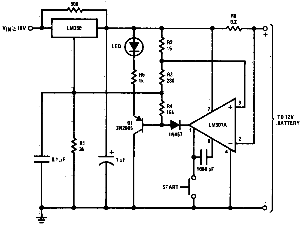
DC 12V Battery Charger Circuit Diagram. This circuit is a high-performance charger for gelled electrolyte lead-acid batteries. The DC 12V battery charger circuit is designed to efficiently charge gelled electrolyte lead-acid batteries, which are commonly used in various applications due...
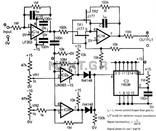
Low-frequency signals produced by transducers, measurement equipment, or data loggers often resemble the first waveform in the figure. The circuit operates as a tracking sample-and-hold, where transients are replaced in the output by the stored value of the current...
The wireless FM transmitter circuit described here includes an additional RF power amplifier stage following the oscillator stage, which increases the power output to 200-250 mW. The wireless FM transmitter circuit functions by modulating audio signals onto a radio frequency...