
Solar voltage regulator

U1A compares an adjustable sample of the present battery voltage to a 5V reference from a highly stable source. According to the result, it controls the power transistors Q1 and Q2, which shunt off the excess power generation from the panel. A diode (D1) avoids battery voltage to go back to the panel under no-light condition. To avoid imprecise voltage control due to varying diode drop, the sample is taken from the battery side, even if this means a very small power waste.
The power resistors R1 and R2 are dimensioned in such a way that under maximum shunting, these resistors will dissipate almost all power (about 100W total), leaving the transistors running cool. The highest dissipation in the transistors happens when the regulator is dissipating half of the panel output; in this case, each transistor will dissipate about 12W.
U1B is a Schmitt trigger that compares the battery voltage to the same stable reference of the other section, but for another purpose: It controls the load switch Q3. This circuit will disconnect the load if the battery gets close to deep discharge, and reconnect it only when recharge is well underway. The negative side of the load is switched, simply because N-channel MOSFETs are much cheaper and better than P-channel ones.
Component notes:
D1 can be any diode that can safely survive the panel's current. If the panel has a very low voltage output (less than 33 cells in series), it is an advantage to employ a Schottky diode in this place. Q1 and Q2 are common power Darlington transistors. They need to be heatsinked for safe long-term operation at the 12 Watt dissipation level. That's easy enough to do, but many newcomers misjudge how much thermal resistance is introduced by a mica insulator! Plan on 1K/W thermal resistance inside each transistor, two times as much in the insulator (if you use any), and 370K safe junction temperature. For typical environmental conditions, this makes you need a heatsink having a thermal resistance of about 1.3K/W. If it is larger, you get more safety margin.
R1 and R2 will have to be made by combining a number of power resistors in parallel. Yes, you need to make two resistor arrays of 4 Ohm, 80W each! This 80W figure includes a reasonable safety margin. These resistors will produce a lot of heat, and you may cook your coffee on them! Be sure to mount them in such a way that they have lots of ventilation, and that the heat from them will not reach the other components.
R3 and R4 may to have be built from parallel combinations too, because of the low value of only 0.15 Ohm.
U2 is a voltage reference IC. You cannot replace it by a standard Zener diode! Zeners are much too unstable! If you can't find this chip locally, you may use the ubiquitous 7805 regulator instead, but the power drain from the battery will be higher. In this case, of course you don't need R8, but you would need a 1uF capacitor at the 7805 output.
Q3 is a power MOSFET that has a very low Rds(on). You may use a different one, provided that it has a resistance that's low enough for your application. You may use several in parallel. The one used has low loss even at loads of 20A, and can handle much more.
The circuit operates effectively by maintaining a constant output voltage while managing the energy produced by the solar panel. The linear shunt regulator ensures that excess energy is dissipated, preventing overcharging of the battery and prolonging its life. This is particularly crucial for lead-acid batteries, which are sensitive to deep discharges. By employing a combination of transistors and a Schmitt trigger, the design provides reliable load management and battery protection. The use of power resistors designed to handle significant thermal loads ensures the transistors operate within safe limits, enhancing the overall efficiency and durability of the system. The choice of components, such as the diode and voltage reference, plays a vital role in maintaining circuit stability and performance under varying conditions. The design can be adapted for higher current applications, making it versatile for different solar energy systems.The circuit presented here uses linear shunt regulation. Simply spoken, it burns off all excess energy from the panel, keeping output voltage constant. At times when the solar panel output is equal or greater than the load, and the battery is fully charged, the load gets its power from the panel, while the battery rests at full charge. Five years battery lifetime are entirely normal with this system, while the same batteries last only two to three years when used with pulsing regulators!
The second responsibility of the regulator is watching over the battery voltage, and dropping off the load when the battery gets discharged too much. Lead batteries are severely damaged by deep discharges, so it's far preferable to drop off the load, then to have the battery die in a bad weather spell.
You may want to print it out, and then go on reading. This regulator is designed for 12V systems employing panels of up to 7A total current, and loads of not over 20A. It can be easily modified for greater currents. U1A compares an adjustable sample of the present battery voltage to a 5V reference from a highly stable source.
According to the result, it controls the power transistors Q1 and Q2, which shunt off the excess power generation from the panel. A diode (D1) avoids battery voltage to go back to the panel under no-light condition. To avoid imprecise voltage control due to varying diode drop, the sample is taken from the battery side, even if this means a very small power waste.
The power resistors R1 and R2 are dimensioned in such a way that under maximum shunting, these resistors will dissipate almost all power (about 100W total), leaving the transistors running cool. The highest dissipation in the transistors happens when the regulator is dissipating half of the panel output; in this case, each transistor will dissipate about 12W.
U1B is a Schmitt trigger that compares the battery voltage to the same stable reference of the other section, but for another purpose: It controls the load switch Q3. This circuit will disconnect the load if the battery gets close to deep discharge, and reconnect it only when recharge is well underway.
The negative side of the load is switched, simply because N-channel MOSFETs are much cheaper and better than P-channel ones. Component notes: D1 can be any diode that can safely survive the panel's current. If the panel has a very low voltage output (less than 33 cells in series), it is an advantage to employ a Schottky diode in this place.
Q1 and Q2 are common power Darlington transistors. They need to be heatsinked for safe long-term operation at the 12 Watt dissipation level. That's easy enough to do, but many newcomers misjudge how much thermal resistance is introduced by a mica insulator! Plan on 1K/W thermal resistance inside each transistor, two times as much in the insulator (if you use any), and 370K safe junction temperature.
For typical environmental conditions, this makes you need a heatsink having a thermal resistance of about 1.3K/W. If it is larger, you get more safety margin. R1 and R2 will have to be made by combining a number of power resistors in parallel. Yes, you need to make two resistor arrays of 4 Ohm, 80W each! This 80W figure includes a reasonable safety margin. These resistors will produce a lot of heat, and you may cook your coffee on them! Be sure to mount them in such a way that they have lots of ventilation, and that the heat from them will not reach the other components.
R3 and R4 may to have be built from parallel combinations too, because of the low value of only 0.15 Ohm. U2 is a voltage reference IC. You cannot replace it by a standard Zener diode! Zeners are much too unstable! If you can't find this chip locally, you may use the ubiquitous 7805 regulator instead, but the power drain from the battery will be higher.
In this case, of course you don't need R8, but you would need a 1uF capacitor at the 7805 output. Q3 is a power MOSFET that has a very low Rds(on). You may use a different one, provided that it has a resistance that's low enough for your application. You may use several in parallel. The one I used has low loss even at loads of 20A, and can handle much more! 🔗 External reference
Related Circuits
Switching to alternative power sources can help reduce electricity bills. The photovoltaic module or solar panel described here is capable of generating renewable energy. The photovoltaic module, commonly known as a solar panel, is a device that converts sunlight into...
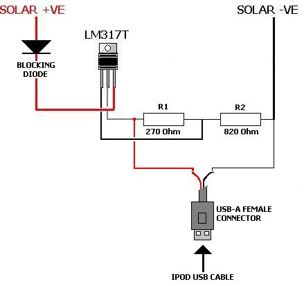
A solar charger for an iPod is no more difficult than creating a solar battery charger. Built-in iPod batteries operate at 3.7 Volts, with capacity (measured in mAh) varying by iPod model—e.g., 1,200mAh for a 2nd Gen, 850mAh for...
This is a straightforward circuit designed for charging lead-acid batteries using the PB137 regulator. The PB137 is utilized in the lead-acid battery charger circuit due to its ability to provide... The PB137 voltage regulator is a linear regulator specifically suited...
The Car Voltage Gauge is based on 3 parts. The input circuit is an Analog to Digital Converter (IC2 CA3162E). The purpose of this chip is to sample an analog voltage and convert it to a decimal value which...
This is a simple NiCd battery charger powered by solar cells. A solar cell panel or an array of solar cells can charge a battery at more than 80% efficiency. The described circuit functions as a basic NiCd battery charger...
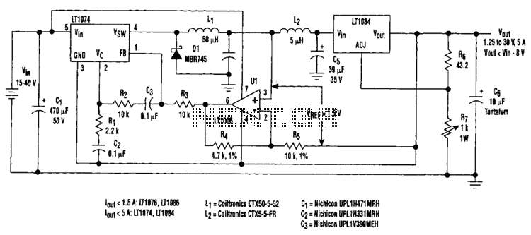
Large input-to-output voltage differentials, caused by wide input voltage variations, reduce a linear regulator's efficiency and increase its power dissipation. A switching preregulator can reduce this power dissipation by minimizing the voltage drop across an adjustable linear regulator to...