
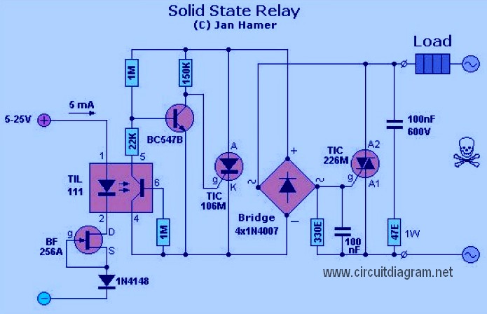
solid state relay
Amplifier components include:
- P1 = 22K Log Potentiometer (Dual-gang for stereo)
- R1 = 1K 1/4W Resistor
- R2 = 4K7 1/4W Resistor
- R3 = 100R 1/4W Resistor
- R4 = 4K7 1/4W Resistor
- R5 = 82K 1/4W Resistor
- R6 = 10R 1/2W Resistor
- R7 = R22 4W Wirewound Resistor
This circuit is inexpensive, simple, and can be used as a general audio amplifier for devices such as computers or CD players with headphone outputs. The design intentionally avoids integrated circuits, opting for a traditional approach to achieve desirable harmonic distortion characteristics.
Additionally, there is a heat detector circuit integrated with a siren circuit. This circuit utilizes a complementary pair of transistors: an NPN metallic transistor (T1, BC109) and a PNP germanium transistor (T2, AC188) to detect heat, such as that from a fire, and activate an alarm.
The automatic emergency light circuit schematic is controlled using an integrated circuit (IC). Its primary features include automatically turning on the light during a power outage and a battery charger with overcharge protection. When mains power is lost, relay RL2 remains de-energized, providing DC power.
A high-fidelity audio amplifier circuit diagram is also included, which does not require a preamplifier. The component list is as follows:
- R1, R4 = 47K 1/4W Resistors
- R2 = 4K7 1/4W Resistor
- R3 = 1K5 1/4W Resistor
- R5 = 390R 1/4W Resistor
- R6 = 470R 1/4W Resistor
- R7 = 33K 1/4W Resistor
- R8 = 150K 1/4W Resistor
- R9 = 15K 1/4W Resistor
The combination of these circuits illustrates a variety of electronic applications ranging from audio amplification to safety systems, showcasing the versatility and effectiveness of simple electronic designs.A Solid State Relay is in reality not a relay after all. There`s no `relay` found, just the electronics circuit which does the switching. It operates a similar way as a relay; it is possible to use a low voltage to switch a higher voltage or better than ordinary relay. This `relay` is placed in. This circuit diagram is quite simple and cheap. Amp lifier parts: P1 = 22K Log. Potentiometer (Dual-gang for stereo) R1 = 1K 1/4W Resistor R2 = 4K7 1/4W Resistor R3 = 100R 1/4W Resistor R4 = 4K7 1/4W Resistor R5 = 82K 1/4W Resistor R6 = 10R 1/2W Resistor R7 = R22 4W Resistor (wirewound) R8 =. This circuit is inexpensive, easy and quite simple. This is general audio amplifier which can be used for computer, CD player or other devices which have headphone output.
The circuit was deliberately designed using no ICs and in a rather old-fashioned manner in order to obtain good harmonic distortion behaviour and to avoid hard to. This is the diagram of heat detector circuit which already integrated with siren circuit in the output.
This circuit applies a complementary pair comprising NPN metallic transistor T1 (BC109) and PNP germanium transistor T2 (AC188) to detect heat (because of outbreak of fire, for example) in the area and activate a siren/alarm. The collector of. The schematic diagram shown right here is the automatic switching-on emergency light circuit which is controlled using IC.
The most important capabilities of this circuit are: automatic switching-on of the light on main power failure and battery charger with overcharge protection. When mains electrical power is absent, relay RL2 is in deenergised state, feeding DC. This is high fidelity, high quality audio amplifier circuit diagram. You don`t need pre amplifier. Component list: R1, R4 = 47K 1/4W Resistors R2 = 4K7 1/4W Resistors R3 = 1K5 1/4W Resistors R5 = 390R 1/4W Resistors R6 = 470R 1/4W Resistors R7 = 33K 1/4W Resistors R8 = 150K 1/4W Resistors R9 = 15K.
🔗 External reference
Related Circuits
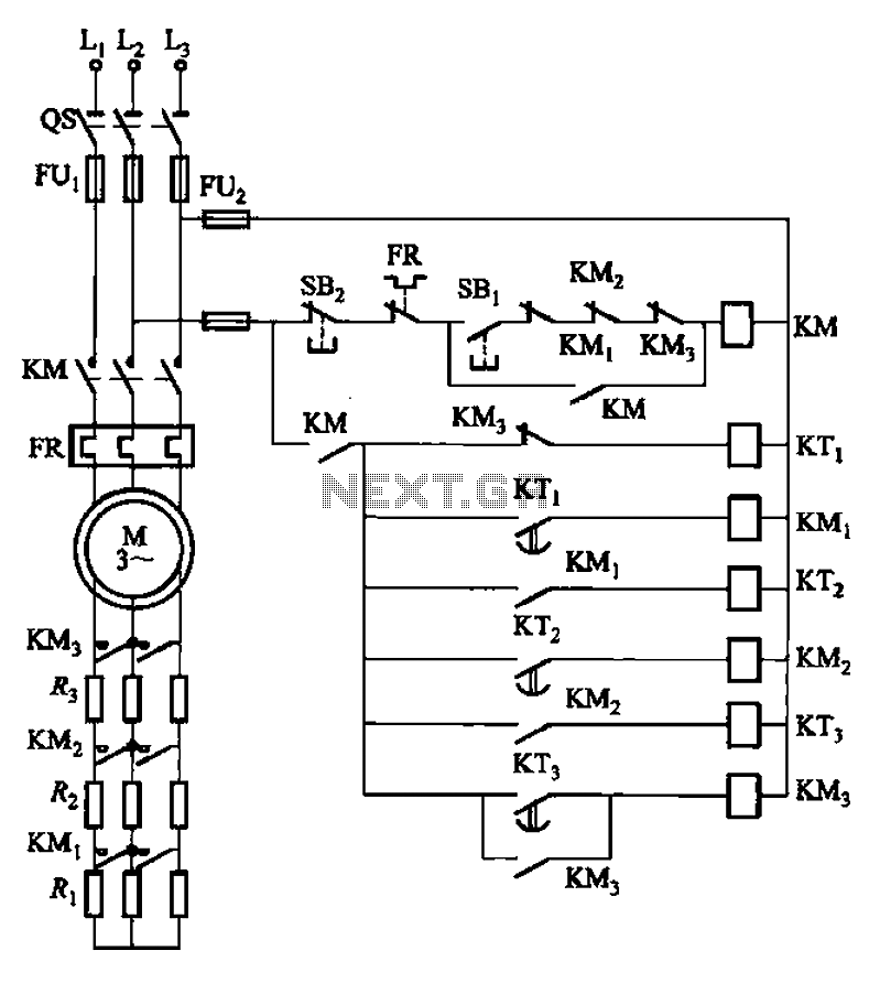
The circuit depicted in Figure 3-159 employs complementary operation three times along with three relay contacts. This is followed by the automatic elimination of the rotor circuit resistance levels, ultimately reducing the rotor winding variable resistor to zero (fully...
A relay (RL1) is activated with a 100-second delay when a +12V power supply is connected to the circuit. Figure 2 illustrates a relay timer circuit utilizing a 555 timer, featuring two time ranges: 6-60 seconds and 1-10 minutes...
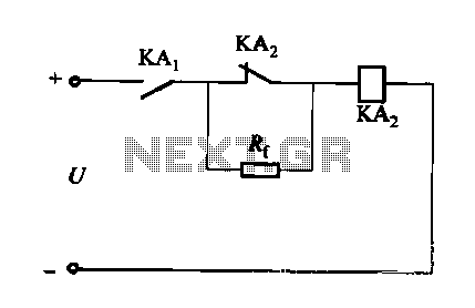
A DC relay or contactor is utilized to enhance the excitation pull-in and release mechanisms in a circuit. The relay circuit, as depicted in Figure 6-28, facilitates improved return line efficiency. When the control relay KAi is activated, its...
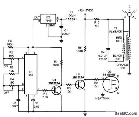
A TV flyback transformer can function as a low-power Tesla coil. The Tesla circuit is comprised of a pulse generator, a driver circuit, and a high-voltage transformer. Resistors R1 and R2 control the duration for which the output at...
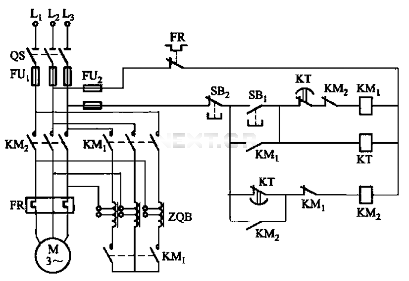
The circuit depicted in Figure 3-49 illustrates an autotransformer that is controlled by a time relay (KT). The delay time set by the KT relay corresponds to the motor's startup duration. The circuit utilizes an autotransformer, which is a type...
In this circuit, two transistors are configured as a high-gain compound pair. Transistor T1 is likely a 2N2222A, while T2 is identified as a BC108. The current gain is calculated as the product of the beta values of each...