
Relay Timer switch circuit
The circuit described employs a 555 timer IC configured in a monostable mode to create a delay function. When the circuit is powered with a +12V supply, the timer initiates a countdown for 100 seconds, after which it energizes relay RL1, allowing it to close its contacts and complete a secondary circuit.
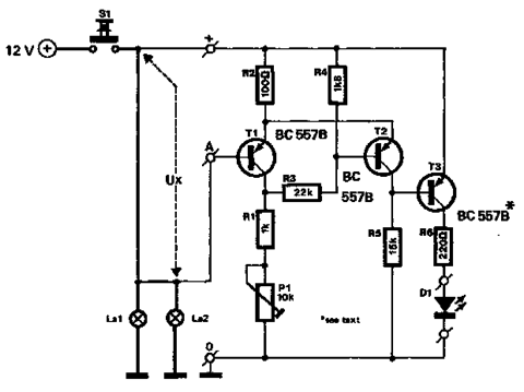
For the timer circuit depicted in Figure 2, the 555 timer can be adjusted to provide two selectable time ranges. The first range allows for delays from 6 to 60 seconds, while the second range extends the delay from 1 to 10 minutes. This is achieved by incorporating variable resistors (potentiometers) and capacitors that determine the timing intervals.
The configuration of the 555 timer includes a resistor connected to the discharge pin and a capacitor connected to the threshold pin, which sets the timing period. The output from the 555 timer drives the relay coil of RL1, ensuring that it remains activated only for the duration set by the timing components.
In summary, this relay timer circuit provides a versatile solution for applications requiring delayed activation, leveraging the reliability of the 555 timer IC to achieve precise timing control over the relay operation.A 100 second delayed turn ON relay RL1 switch, if plug power +12V in circuit. In Fig. 2 see a two range 6-60 second and 1-10 minute auto turn off relay timer circuit, with 555. 🔗 External reference
Related Circuits
What exactly is a multivibrator? I suppose one definition would be 'a circuit which has several states'. This will do for now, it's quite loose so leaves plenty to the imagination! Conventional multivibrators have only two stages and come...
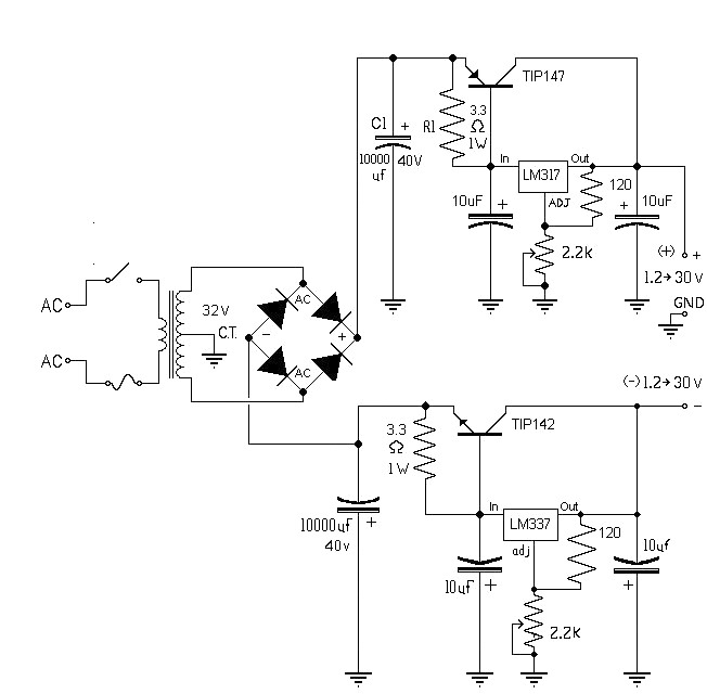
The 10A variable power supply circuit is symmetrical and can provide a symmetrical output voltage ranging from ±1.2 volts to ±30 volts DC, with a maximum current of 10A. This circuit utilizes symmetrical variable voltage regulators LM317 and LM337,...
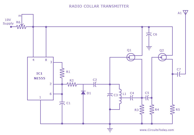
This is a radio transmitter circuit diagram designed for integration into radio collars using the NE 555 integrated circuit. The circuit transmits a pulse in the FM band, specifically between 88 MHz and 105 MHz. The radio transmitter circuit utilizes...
A new user has joined the forum and is seeking assistance with circuit design. They express a desire for guidance and acknowledge their inexperience in the subject. In circuit design, it is crucial to understand the fundamental components and their...
The L29 Stepper Motor Controller IC facilitates the control of four drive signals for two bipolar and four unipolar footfall motors in a microcomputer-controlled appliance. It allows for motor operation in half-step, full-step, and wave drive modes, utilizing switch-mode...
The circuit described below monitors the car's brake lights and indicates their operational status using a 12V light-emitting diode (LED). This functionality can prevent fines for driving with defective brake lights and enhance road safety. The monitor relies on...