
DC relay circuit to accelerate the release
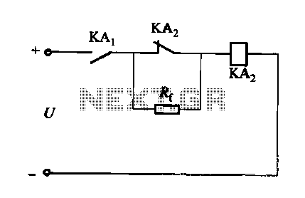
The described circuit employs a DC relay or contactor to optimize the operation of the relay system. The relay, designated as KAi, serves as the primary control element, engaging its normally closed contact at the moment of activation. This engagement allows for the energization of a secondary relay, KAz, which plays a crucial role in the release phase of the circuit operation.
Upon activation of KAi, the circuit configuration ensures that the KAz coil is energized without creating a return path through KAi. This design prevents any undesirable feedback that could hinder performance. The acceleration of the release process is achieved through the interaction between KAi and KAz, where KAz is specifically designed to assist in quickly disengaging the load once KAi is turned off.
The adjustment of the return coefficient, Rf, is critical to the overall performance of the relay circuit. By fine-tuning Rf, the wind resistance of the relay can be optimized, enhancing the speed and efficiency of the release mechanism. It is important to maintain Rf within a specified range, ideally between 1 to 2 times the resistance of the relay coil, RL, to ensure reliable operation without overloading the circuit.
This configuration not only improves the efficiency of the relay operation but also minimizes wear and tear on the mechanical components by providing a more controlled release action. The resulting system is more responsive and reliable, suitable for applications where quick actuation and release are essential.DC relay or contactor in addition to using strong excitation pull way accelerate, accelerate the release, but also the following circuit to achieve the purpose of accelerating the release. Circuit shown in Figure 6-28. The relay circuit can improve the return line number. When the control relay KAi (not shown) pulls in, the result of K normally closed contact initially closed. KAz coil is energized, people avoid string coil back road, so when KAi release, KAz will accelerate the release.
Additional value can be adjusted to change the wind resistance of the relay returns coefficient, Rf but not too large, about 1 to 2 times the relay coil resistance RL.
Related Circuits
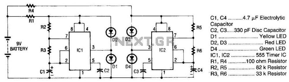
The super LED flasher consists of two complete LED flasher circuits integrated onto a single circuit board. The first LED flasher is comprised of IC1 and LEDs D1 and D2. IC1 is a 555 timer IC configured as an...
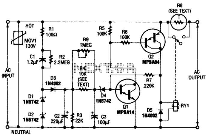
Q1 is an NPN Darlington transistor, and Q2 is a PNP Darlington transistor. MOV1 is a metal-oxide varistor, while R8 is a thermistor used for limiting inrush current. This circuit is designed to limit AC line current to a...
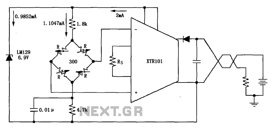
The circuit utilizes the LM129 voltage regulator to produce a 6.9V voltage reference, supplying a current of 1.0147mA from the 6.9V reference voltage to the bridge. The bridge may consist of varistor-type pressure sensors. The LM129 voltage regulator is a...
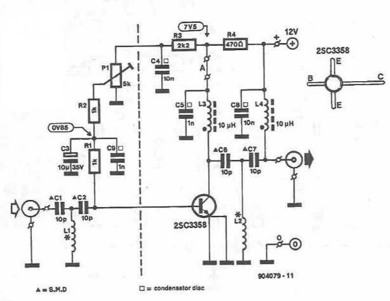
This UHF amplifier circuit project is beneficial for enhancing weak TV signals. The amplifier provides a gain of 10-15 dB within a frequency range of 400 to 850 MHz. To ensure optimal performance and reliability, the PCB tracks should...
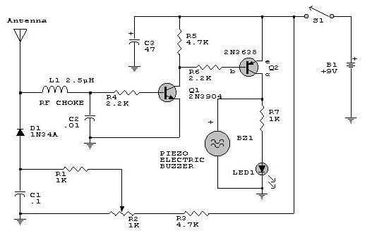
This electronic RF detector project is constructed using common transistors and a few standard electronic components. The RF detector is capable of responding to RF signals below the standard broadcast band and extending to over 500 MHz, providing both...
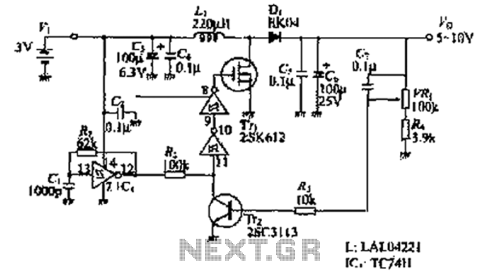
The design of the power supply circuit diagram utilizes an oscillator circuit from the 74HC series of CMOS logic circuits, with a MOSFET as the switching device. This configuration allows for the development of small-scale power supplies suitable for...