
EL Lamp Driver Using HV832MG
The typical lamp consists of light emitting phosphor sandwiched between two conductive electrodes with one of the electrodes transparent so allowing light to escape. As an AC voltage is applied to the electrodes, the electrical ¬eld causes the phosphor to rapidly charge and discharge, resulting in the emission of light during each cycle.
Since the number of light pulses depends on the magnitude of the applied voltage, the brightness of EL lamps can generally be controlled by varying the operating voltage. Because EL lamps are a laminate, they exhibit a capacitance of the order of 2. 5 nF to 3. 5 nF per square inch. When high voltage is applied across the electrodes, the resulting electric ¬eld excites the phosphor atoms to a higher energy state.
When the electric ¬eld is removed, the atoms fall back to a lower energy state, emitting photons in the process. The wavelength of the emitted light is determined by the type of phosphor used and the frequency of the excitation voltage.
With most phosphors, the spectrum of emitted light will tend to shift towards blue with an increase in excitation frequency. Color is usually controlled, however, by selecting the phosphor type, by adding fluorescent dyes in the phosphor layer, through the use of a color filter over the lamp, or a combination of these.
EL lamp brightness increases approximately with the square of applied voltage. Increasing frequency, in addition to affecting hue, will also increase lamp brightness, but with a nearly linear relationship. Most lamp manufacturers publish graphs depicting these relationships for various types of lamps. Excitation voltages usually range from 60 VPP to 200 VPP at 60 Hz to 1 kHz. Increased voltage and/or frequency, however, adversely affects lamp life, with higher frequencies generally decreasing lamp life more than increased voltage.
EL lamps, unlike other types of light sources, do not fail abruptly. Instead, their brightness gradually decreases through use. For intermittent use, lamp life is seldom a concern. For example, if a lamp is used 20 minutes per day, over the course of 10 years the lamp will be activated for a total of 1, 216 hours, well within the useful life of almost any EL lamp available. When designing a drive circuit, a balance needs to be struck between lamp brightness, hue, useful life, and supply current consumption.
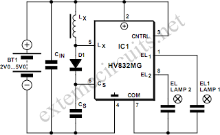
To generate the high voltages needed for driving EL lamps, dedicated ICs like the Supertex HV832MG employ switch-mode converters using inductive ¬‚yback. By integrating high voltage transistors on-chip, this driver avoids the need for expensive, bulky, and noisy transformers to generate high output voltages.
The HV832MG employs open-loop conversion. This EL driver incorporates a lamp drive oscillator that is separate from the power conversion oscillator. This allows setting lamp drive frequency independently from the power conversion frequency and so optimize overall performance.
The power conversion cycle begins when a MOSFET switch in the HV832MG is turned on and current begins to rise in inductor Lx. When the switch is turned off, inductive ¬‚yback causes the voltage across the inductor to reverse polarity and rise until it reaches the level of the storage capacitor CS, (plus diode drop) at which point the rectifier conducts and the energy contained in the magnetic ¬eld of the inductor is transferred to CS.
When all the inductor energy is transferred and inductor current drops to zero, the rectifier stops conducting and inductor voltage drops to zero, ready for the next cycle. Output power is simply the amount of energy transferred per cycle multiplied by the number of cycles per second.
It is important to select the inductor and conversion frequency to provide the required output voltage while assuring that the inductor current does not approach saturation levels. If the inductor saturates, excessive current will flow, potentially leading to device failure. Ideally, the inductor current should be allowed to return to zero between cycles. If inductor current is not allowed to return to zero, a higher average current will be needed to meet output power requirements, increasing I2R losses, and decreasing conversion efficiency.
On he other hand, if too much time is allowed between zero inductor current and the start of the next cycle, more energy will need to be transferred each cycle to maintain output power, thus risking inductor saturation and increasing I2R and core losses. This circuit provides an output of 130 volts at 300-450 Hz, draws just 30mA current, yet is capable of driving EL lamps with a surface area of up to 9 cm2.
This design has excellent drive capability and provides a symmetrical bipolar drive, resulting in a zero-bias signal. Many lamp manufacturers recommend a zero-bias drive signal to avoid potential migration problems and increase lamp life.
The supply voltage should be bypassed with a capacitor located close to the lamp driver. Values can range from 0. 1 µF to 1 µF depending on supply impedance. For very large lamps representing much larger capacitances, a FET follower circuit may be employed to boost the output drive capability of the lamp driver. The HV832MG may be obtained from Supertex Semiconductors, USA, 🔗 External reference
Related Circuits
The IR photo transistor Q1 (Radio Shack 276-145A) or a similar component is connected to the set input (pin 6). It is essential to shield the photo transistor from direct light to ensure that the voltage at the set...
Assistance is required for a final year project involving the design of a grid-connected inverter. The focus is on developing a full bridge inverter circuit. The grid-connected inverter is a crucial component in renewable energy systems, particularly in solar photovoltaic...
Electronics tutorial on combinational logic circuits that utilize logic gates to create multiplexers, encoders, and solid-state switches. Combinational logic circuits are fundamental components in digital electronics, characterized by their ability to produce outputs based solely on the current inputs, without...
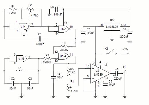
The NAND gates utilize a CMOS 4011 chip, which is a low-power component ideal for battery-operated circuits. This chip is powered by a 5V voltage supplied from an LM7805L regulator. The purpose of this regulation is to maintain a...
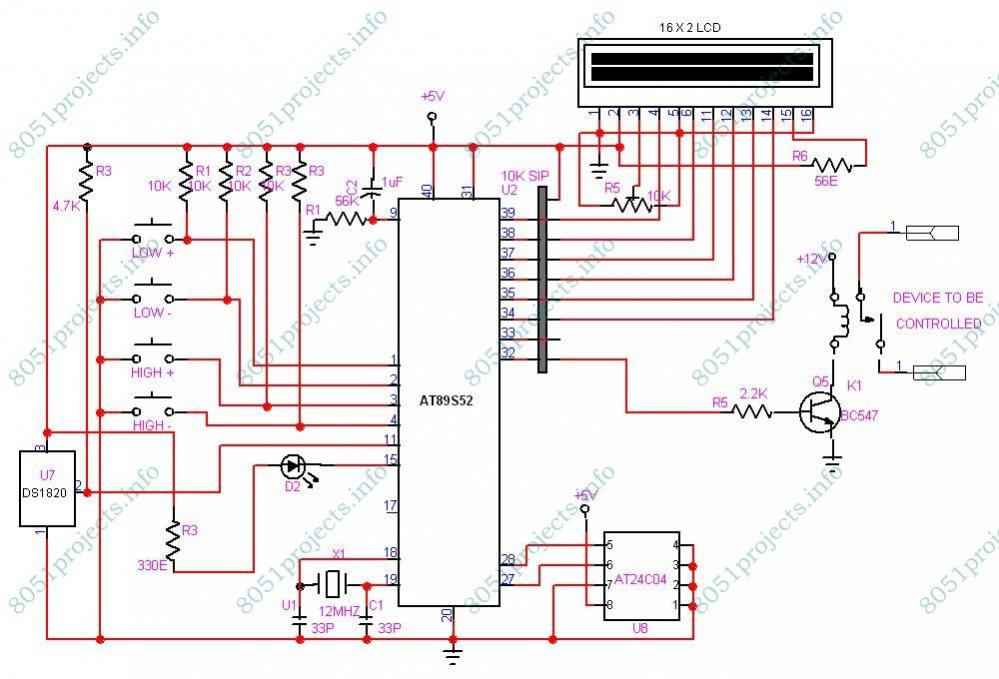
This project is designed to monitor and control temperature. The system utilizes the DS1820 temperature sensor to measure the temperature, which is then displayed on an LCD. It features two preset levels: a low preset and a high preset....
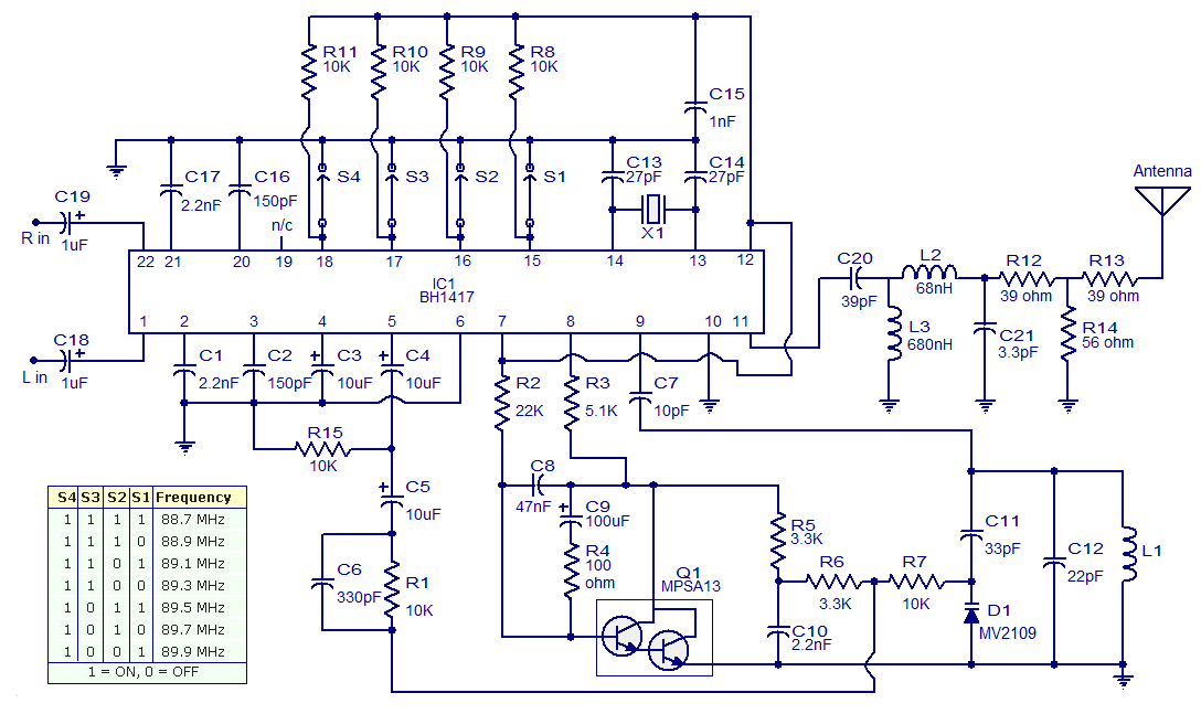
The circuit presented is a simple stereo FM transmitter capable of transmitting high-quality signals over a range of 70 feet. It utilizes the BH1417 PLL Stereo Transmitter IC from Rhom, which features distinct sections for audio processing of the...
Warning: include(partials/cookie-banner.php): Failed to open stream: Permission denied in /var/www/html/nextgr/view-circuit.php on line 713
Warning: include(): Failed opening 'partials/cookie-banner.php' for inclusion (include_path='.:/usr/share/php') in /var/www/html/nextgr/view-circuit.php on line 713