
Voice music outlet circuit diagram SK- made
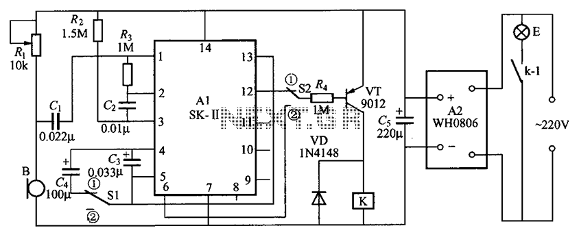
The described circuit integrates several key components, each serving a distinct function to achieve the desired operational characteristics.
1. **Acoustic Sensor**: This component detects sound waves and converts them into electrical signals. It is essential for capturing audio input, which will be processed by the subsequent circuits.
2. **SK Voice Circuit**: This circuit is designed to process the signals received from the acoustic sensor. It typically includes amplification and filtering stages to enhance the quality of the audio signal before it is passed on to the relay control circuit.
3. **Relay Control Circuit**: The relay control circuit acts as a switch that can be activated by the processed audio signals. When the acoustic sensor detects sound and the SK voice circuit processes it, the relay may be triggered to perform a specific action, such as turning on a device or activating another circuit.
4. **Vocal Music Circuit**: This circuit may serve to generate vocal music or sound effects based on the input received from the SK voice circuit. It can include various sound synthesis techniques to produce the desired audio output.
5. **AC Buck Rectifier Circuit**: This component is responsible for converting alternating current (AC) to direct current (DC). The buck rectifier ensures that the power supply is stable and suitable for the operation of the circuit components, particularly the relay and audio circuits.
The integration of these components allows for a versatile circuit capable of responding to acoustic signals and generating appropriate outputs, making it suitable for applications such as sound-activated devices, alarms, or interactive sound systems. Proper attention to the design and layout of the circuit will ensure optimal performance and reliability. Circuit As shown, it comprises an acoustic sensor, SK- voice circuit, relay control circuit, vocal music circuit and the AC buck rectifier circuit. BM acoustic/electric transdu cer.
Related Circuits
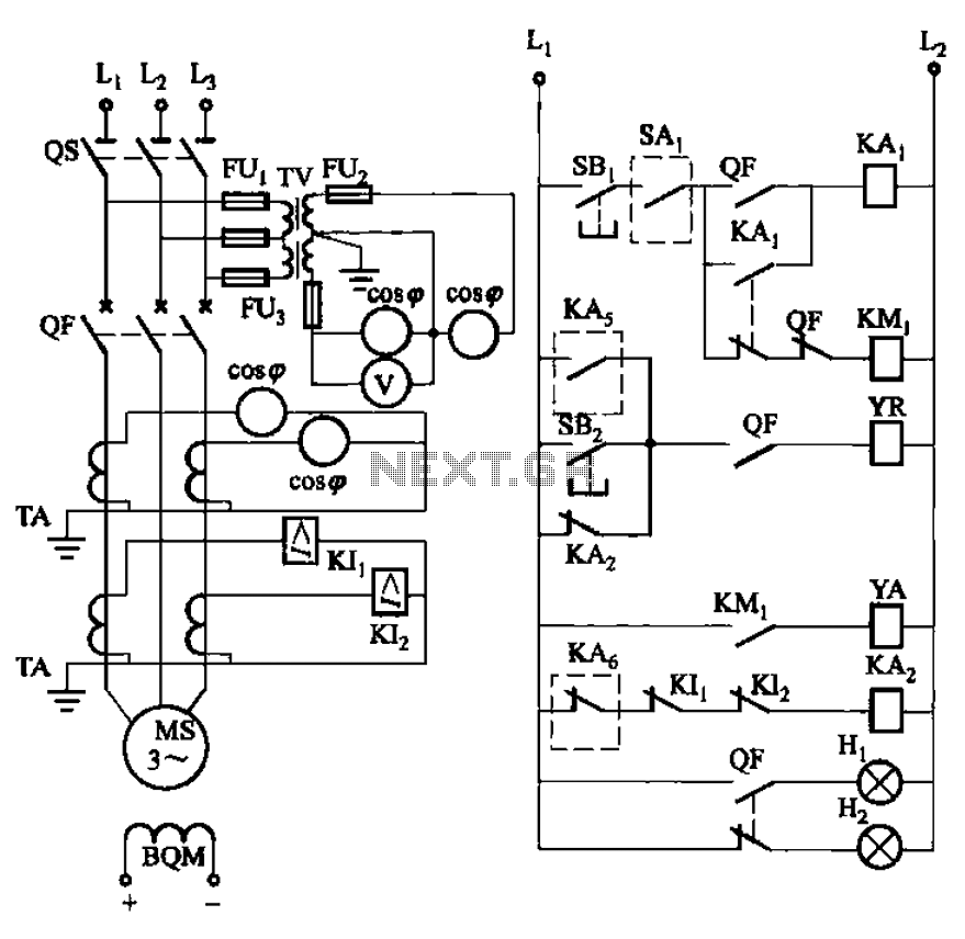
The circuit depicted in Figure 3-186 includes an isolation switch, QF vacuum circuit breakers, YR line for the circuit breaker coil, and YA for the circuit breaker closing coil. Additionally, there is a dashed box representing the excitation device...
Operating radio transmitters without a license is illegal in most countries, so caution is advised with transmitter circuits. This FM low-power circuit is designed to operate within the 87-108 MHz band II, providing a range of approximately 20 to...
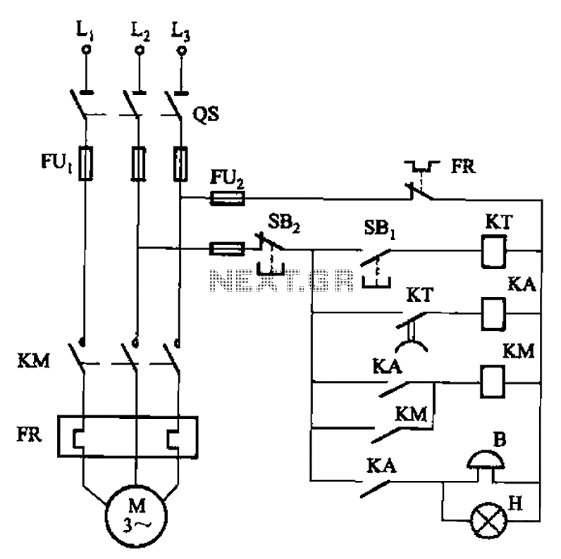
The circuit shown in Figure 3-21 is designed to produce a motor startup sound and a light signal indicating the completion of the startup process, after which the signal ceases. This circuit is tailored to control the motor for...
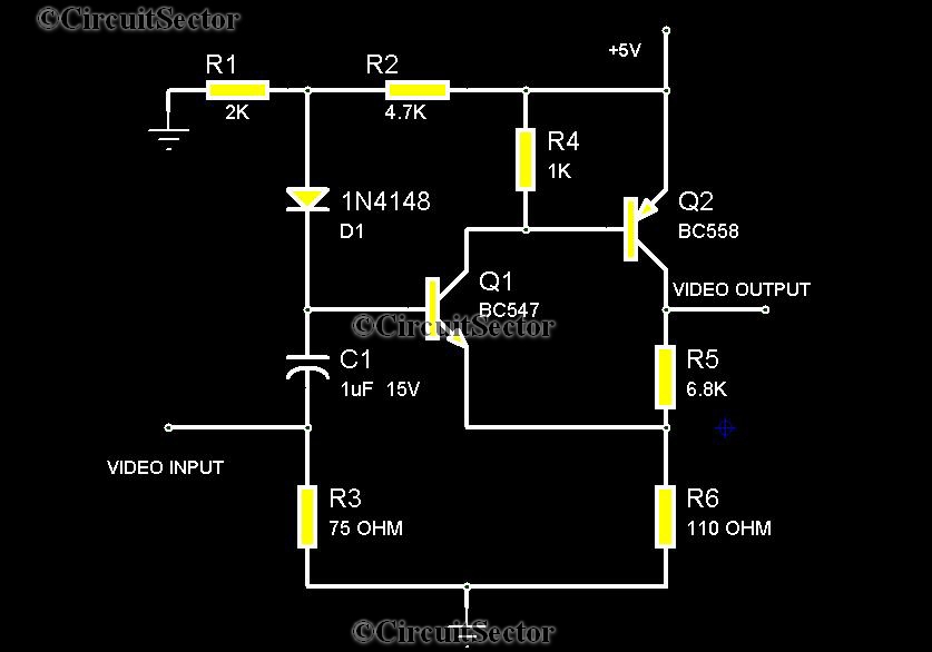
There are instances when it is necessary to view video clips captured by a digital camera on a television. This can be accomplished by connecting the camera's video output to the television's video input. However, a direct connection is...
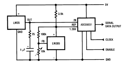
The circuit illustrates a Temperature to Digital Converter diagram utilizing the LM35 sensor, which includes a beneficial bypass capacitor connected from VIN to ground and a series RC damper. The described circuit employs the LM35 temperature sensor, a precision integrated...
The GPS interface can be fed in 2 ways: with a stabilized 5V supply or with a 10 to 25V unregulated DC supply. In both cases, the power is fed into the RJ45 connector on point 8. Pin 7...
Warning: include(partials/cookie-banner.php): Failed to open stream: Permission denied in /var/www/html/nextgr/view-circuit.php on line 713
Warning: include(): Failed opening 'partials/cookie-banner.php' for inclusion (include_path='.:/usr/share/php') in /var/www/html/nextgr/view-circuit.php on line 713