
SOUND I F FOR COLOR TV
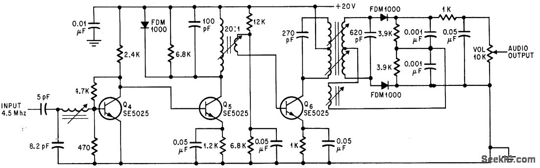
The circuit in question employs a combination of three transistor stages along with a Foster-Seeley discriminator to achieve an audio output of 1 V peak-to-peak. The three transistor stages serve to amplify the audio signal, enhancing its strength and ensuring it reaches the desired output level. Each transistor stage can be configured as a common emitter amplifier, which is effective for voltage amplification while maintaining a reasonable bandwidth.
The Foster-Seeley discriminator is a crucial component in this circuit, primarily used for demodulating frequency-modulated signals. This type of discriminator operates by utilizing the phase relationship between the input signal and a reference signal, allowing it to effectively extract the audio information from the modulated carrier wave. The output of the Foster-Seeley discriminator is then fed into the final transistor stage, which further amplifies the demodulated audio signal to achieve the specified output of 1 V peak-to-peak.
In designing this circuit, attention must be paid to the biasing of each transistor to ensure optimal performance and linearity. Proper selection of resistor values for both the biasing network and the load resistors will be essential in achieving the desired gain and frequency response. Additionally, the layout of the circuit should minimize noise and interference, which can degrade audio quality.
Overall, this configuration illustrates a fundamental approach to audio amplification and demodulation in electronic circuits, showcasing the integration of discrete components to achieve a specific output requirement in audio applications.Uses three transislor stages und Foster-Seeley discriminotor to give audio output of 1 v peak to peak. -D. Bray, Solid State Makes Debut in Big Screen Color Tv, Electronics, 39:8, p 99-105. 🔗 External reference
Related Circuits
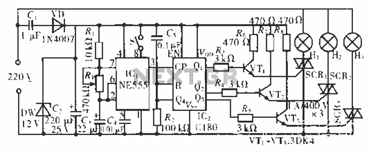
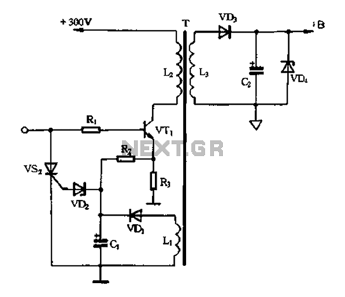
The circuit operates at 220 V AC using a C1 buck converter and a DW regulator. The VD ensures the entire stream is processed, and C2 provides a filtered output of 12 V DC for the voltage supply control...
A piezoelectric sounder (self-drive type) consists solely of a piezoelectric diaphragm with a feedback electrode and is utilized in conjunction with an external drive circuit. The drive circuit for both types of sounders is a simple configuration comprising one...
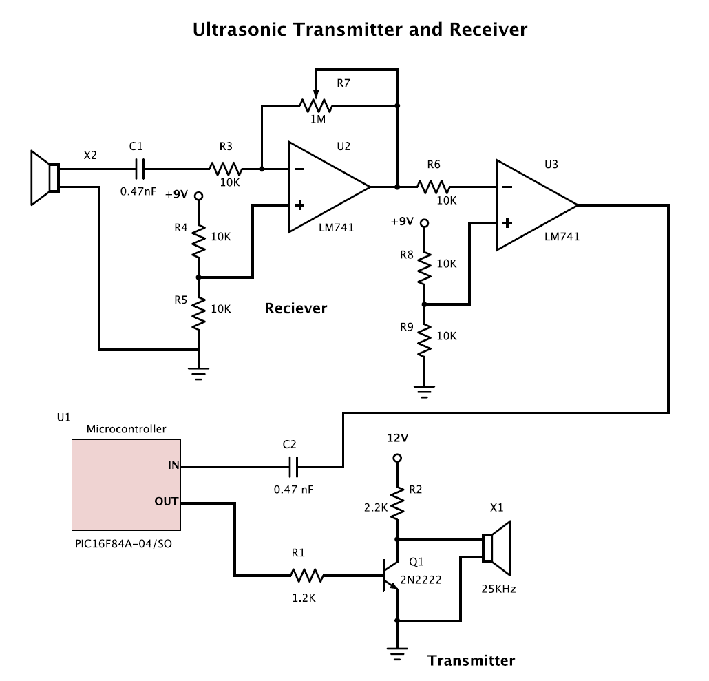
The goal is to create two circuits: one transmitter and one receiver for ultrasound applications. A pair of 25 kHz transmitter and receiver units is already available. To design an ultrasound transmitter and receiver circuit operating at 25 kHz, the...
Many individuals use headphones connected to a computer sound card output to enjoy music or games. It is common for these headphones and microphones to connect to the appropriate slots on the sound card. However, if the female plug...
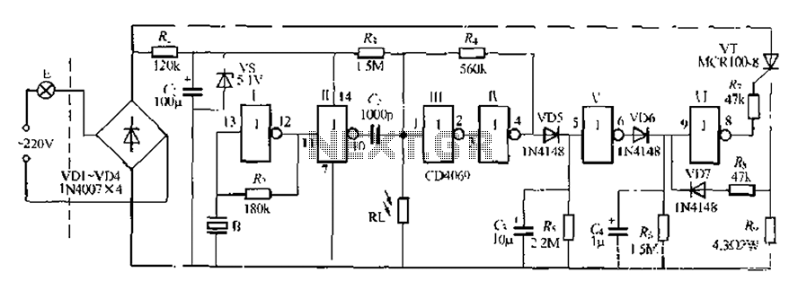
The circuit is designed for sound and light control of stairway and walkway lighting. It features high immunity and includes soft-start and over-current protection mechanisms. During the day, the photosensitive resistor has low resistance, resulting in a low voltage...
Color TV main power protection circuit The color TV main power protection circuit is designed to safeguard the television's power supply from various electrical anomalies, such as overvoltage, undervoltage, and short circuits. This circuit typically employs several components, including fuses,...