
25 kHz Ultrasound Transducer
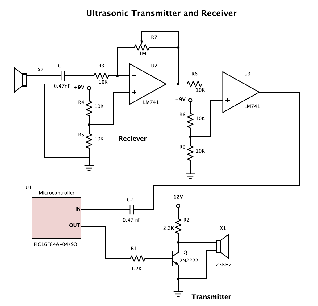
To design an ultrasound transmitter and receiver circuit operating at 25 kHz, the following components and configurations are recommended:
**Transmitter Circuit:**
1. **Oscillator**: A 25 kHz signal can be generated using a 555 timer IC configured in astable mode. The frequency can be set by choosing appropriate resistor and capacitor values (for example, R1 = 1.5 kΩ, R2 = 10 kΩ, and C1 = 10 µF).
2. **Amplifier**: The output from the 555 timer can be fed into a transistor amplifier (such as a NPN transistor) to increase the power of the signal. The transistor should be connected in a common-emitter configuration to boost the output drive capability.
3. **Transducer**: A suitable ultrasonic transducer should be connected to the output of the amplifier. The transducer converts the electrical signal into ultrasonic sound waves. The specifications of the transducer should match the operating frequency of 25 kHz.
4. **Power Supply**: Ensure that the circuit is powered by a stable DC power supply, typically between 5V to 12V, depending on the specifications of the components used.
**Receiver Circuit:**
1. **Transducer**: An ultrasonic transducer that operates at 25 kHz should also be used for receiving the ultrasonic signals. The transducer will convert the incoming ultrasonic waves back into electrical signals.
2. **Amplifier**: The received signal will be weak and should be amplified using an operational amplifier (op-amp) configured in a non-inverting mode. This will help in boosting the signal for further processing.
3. **Bandpass Filter**: A bandpass filter can be implemented to isolate the desired 25 kHz signal from ambient noise. This can be achieved using a combination of capacitors and inductors or using active filtering techniques with op-amps.
4. **Demodulator**: If the transmitted signal is modulated, a demodulator circuit will be necessary to extract the original signal. This can be done using envelope detection or synchronous detection methods.
5. **Output**: The output of the receiver circuit can be connected to a microcontroller or an analog-to-digital converter (ADC) for further processing and analysis of the received signal.
**Considerations**:
- Proper grounding and shielding should be implemented to minimize interference and noise in both circuits.
- Testing and calibration of the circuits are essential to ensure accurate transmission and reception of ultrasonic signals.
- The layout of the circuit on a PCB should consider the placement of components to reduce parasitic capacitance and inductance, which can affect performance at high frequencies.
This comprehensive approach will facilitate the successful development of the transmitter and receiver circuits for ultrasound applications at the specified frequency.I am trying to create two circuits * 1 transmitter * 1 receiver for ultrasounds. I all ready have a pair of 25 kHz transmitter/receiver.. 🔗 External reference
Related Circuits
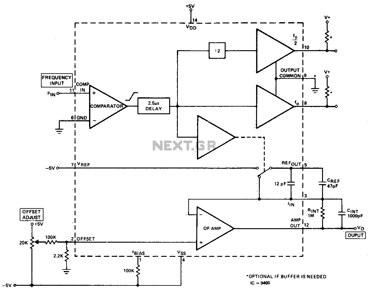
The converter produces an output voltage that is linearly proportional to the input frequency waveform. Each zero crossing at the comparator's input results in a specific amount of charge being dispensed into the op-amp's summing junction. This charge subsequently...
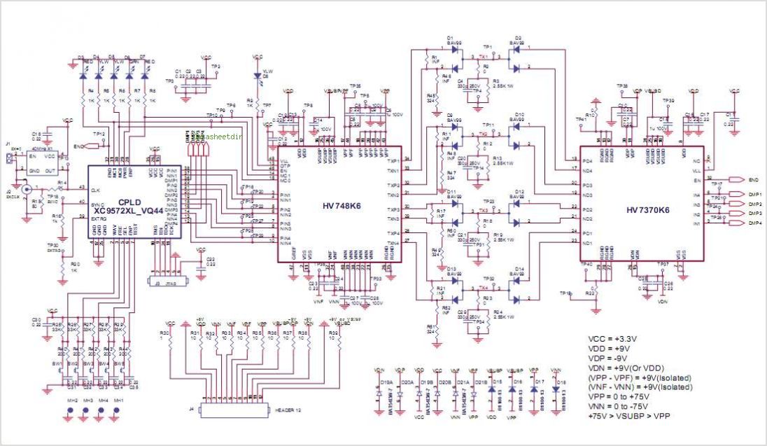
Many TOPSwitch TOP223 flyback power supply applications require two or more outputs to supply a variety of secondary circuits. Typical consumer applications of these multiple output converters include televisions and related products such as set-top decoders and video cassette...
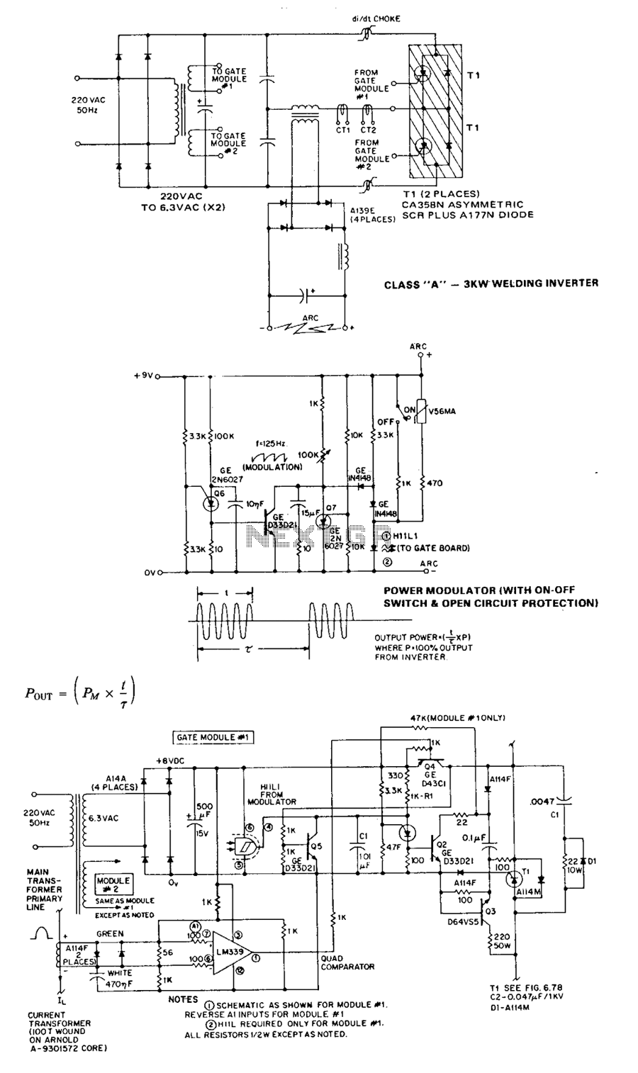
The circuit operates without significant added complexity and has a natural tendency to run away under no-load (high Q) conditions. The 20-kHz control circuit addresses these issues by feeding back into the asymmetrical thyristor trigger pulse generators signals that...
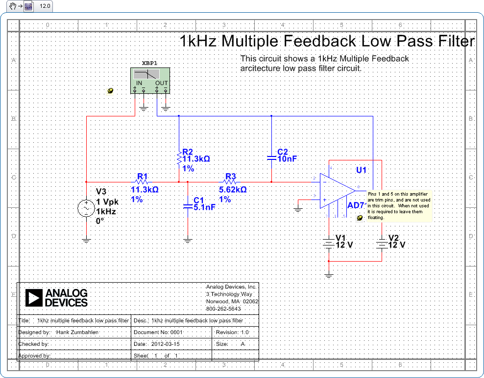
Pins 1 and 5 on this amplifier are trim pins and are not utilized in the circuit. When not in use, it is necessary to leave them floating. In electronic amplifier circuits, trim pins are often included for calibration or...
This circuit is utilized in an impulse speed modulation system. In this system, the transmitter alters the impulse speed of the modulated beam in an optical fiber, allowing it to vary around a center frequency of 50 kHz. The...
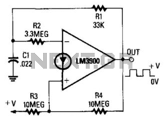
When the output is high, R3 and R4 are in parallel, and C1 charges through R1 until the current in R2 equals that at the non-inverting terminal. This action occurs when C1's voltage rises to 2/3 of the supply...