
Sound level monitor
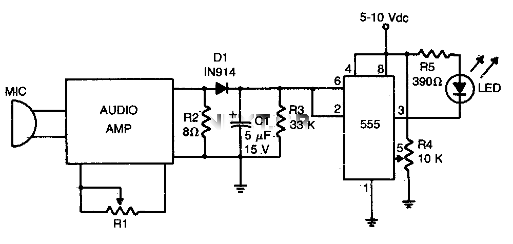
The loudness detector circuit utilizes the 555 timer IC, which is a versatile and widely used component in various electronic applications. When configured as a Schmitt trigger, the 555 IC provides hysteresis in the output, which helps to eliminate noise from the input signal and ensures stable switching behavior.
In this configuration, the input voltage is continuously monitored. When the input voltage rises above the threshold set by the resistor R4, the output of the 555 IC switches from a high state (logic level '1') to a low state (logic level '0'). This transition can be used to trigger other circuits or devices, such as an LED indicator or a sound alert, indicating that a certain loudness level has been detected.
The threshold voltage is critical for the operation of the loudness detector. It is determined by the resistor R4, which is part of a voltage divider network. By adjusting the resistance of R4, the sensitivity of the detector can be modified, allowing it to respond to different levels of input voltage. This feature makes the circuit adaptable for various applications, such as audio processing, sound level monitoring, or automatic gain control systems.
In summary, the loudness detector circuit employing a 555 IC as a Schmitt trigger provides a reliable means of detecting loudness levels by utilizing a threshold voltage established by the resistor R4, thereby facilitating various audio-related applications.Loudness detector consists of a 555 IC wired as a Schmitt trigger. The output changes state—from high to low—whenever the input crosses a certain voltage That threshold voltage is established by the setting of R4. 🔗 External reference
Related Circuits
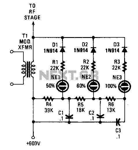
Switching diodes are utilized to activate the neon lamps when negative-peak modulation reaches 50%, 60%, and 100%. To operate the circuit effectively, it is important to monitor the lamps. The 50% lamp should ideally be firing continuously, the 60%...
This sound effects circuit is designed to function as a signal distorter. When utilized with an electric guitar, it enables the creation of unique sound effects. The sound effects circuit operates by manipulating the input audio signal from the electric...
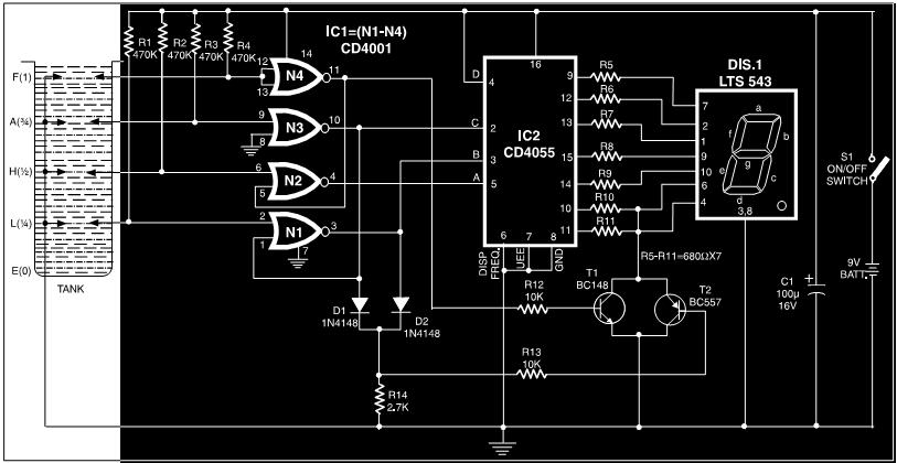
This circuit is a fluid level indicator that displays each level using meaningful English letters. It employs a seven-segment display to represent the letters E for empty, L for low, H for half, A for above average, and F...
This is a surround sound decoder. With this circuit, you can divide the 2-channel (right and left channel) stereo output into 4-channel output, which includes the right channel, left channel, center output, and rear output. This circuit will enhance...
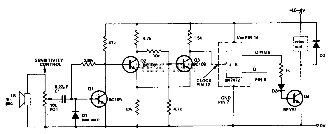
This circuit activates a relay in response to sounds of sufficient intensity. A single clap of the hands will switch the relay in one direction, while a second clap will return the circuit to its original state. Q2 and...
There are many who built the Easy Programmer or C-52 Evaluation Board, asking for the RS232C level converter chip, DS275. Many have changed to MAX232 instead, because it is not available in their home. Here is another simple and...
Warning: include(partials/cookie-banner.php): Failed to open stream: Permission denied in /var/www/html/nextgr/view-circuit.php on line 713
Warning: include(): Failed opening 'partials/cookie-banner.php' for inclusion (include_path='.:/usr/share/php') in /var/www/html/nextgr/view-circuit.php on line 713