
Using kd-28 to do the voice switch circuit diagram
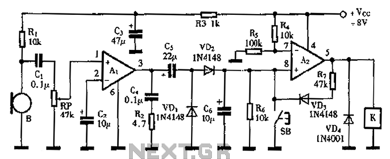
The voice-activated switch circuit utilizes an A1 amplifier configured to enhance audio signals captured by a microphone. The microphone (B) serves as the input transducer, converting sound waves into electrical signals, which are then amplified by A1. The amplified output is processed through a voltage doubler circuit, consisting of capacitors and diodes (C5, VD1, and VD2). This configuration effectively increases the voltage level, allowing capacitor C6 to store sufficient charge when the input audio signal exceeds a predetermined threshold.
The A2 amplifier operates as a comparator, where pin 7 receives the voltage from capacitor C6. Once the voltage surpasses a specific level, it triggers the output at pin 5 to go high, energizing relay K. This relay acts as a switch for external appliances, closing its normally open contacts to provide power. The inclusion of resistor R7 and diode VD3 creates a feedback loop that maintains the output of A2 high, keeping the relay energized even after the initial voice signal has ceased.
The circuit incorporates a manual release mechanism via button SB. When pressed, this button pulls pin 8 of A2 low, causing the output at pin 5 to drop, which subsequently deactivates relay K. This feature allows for manual control of the connected devices, ensuring they can be turned off when desired.
To fine-tune the sensitivity of the microphone and the overall responsiveness of the circuit to voice commands, a potentiometer (RP) is provided. Adjusting this component modifies the threshold at which the A2 amplifier responds to incoming audio signals.
When selecting relay K, it is critical to ensure that its rated operating voltage is approximately 2V lower than the supply voltage (Vcc) to prevent potential damage and ensure reliable operation. This design consideration is essential for maintaining the longevity and functionality of the voice-activated switch system. As shown is a practical voice-activated switch, A1 amplifier connected as a conventional microphone B picked up the audio control signal is amplified. After the amplified signa l through C5, VD1, VD2 voltage doubler rectifier to charge the capacitor C6, when the voice signal is sufficiently large, the charging voltage of 7 feet high and A2 level, then use similar op amp amplifier A2 output high relay K is energized, its normally open contact closure turned the accused appliances. R7 and VD3 amplifier A2 self-locking, so that A2 is always 5 feet high output, ensure attracted state relay.
SB is the release button, when pressed SB, 8 feet to the A2 input low, A2 flip, 5-pin output low, the relay K release. Potentiometer RP used to adjust the sensitivity level of the voice circuit. In the selection of the relay K work should pay attention to their rated voltage should be lower than the supply voltage Vcc of about about 2V.
Related Circuits
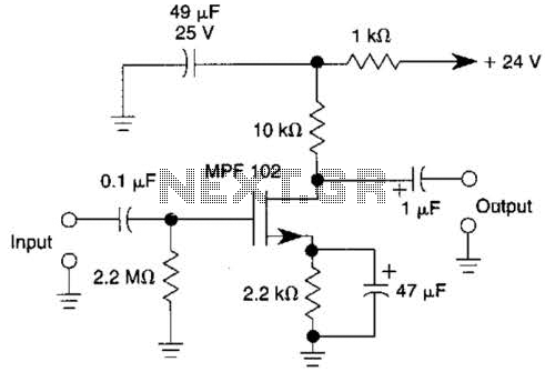
This JFET preamplifier has a gain of approximately 20 dB and a bandwidth exceeding 100 kHz. It is useful as a low-level audio amplifier for high-impedance sources. The described JFET (Junction Field Effect Transistor) preamplifier is designed to amplify low-level...
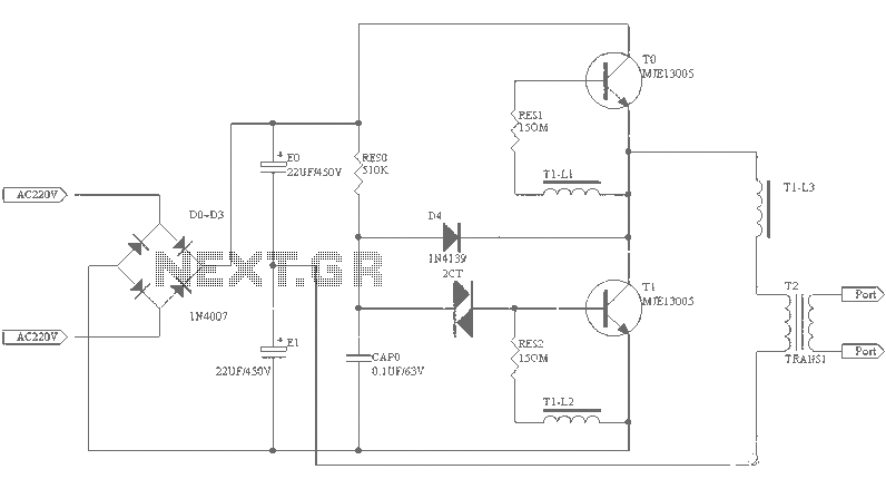
A small (2 to 3 meters) neon electronic transformer circuit diagram is provided below. The described circuit diagram is intended for use with neon lighting systems, specifically those requiring a transformer to operate efficiently within a range of 2 to...
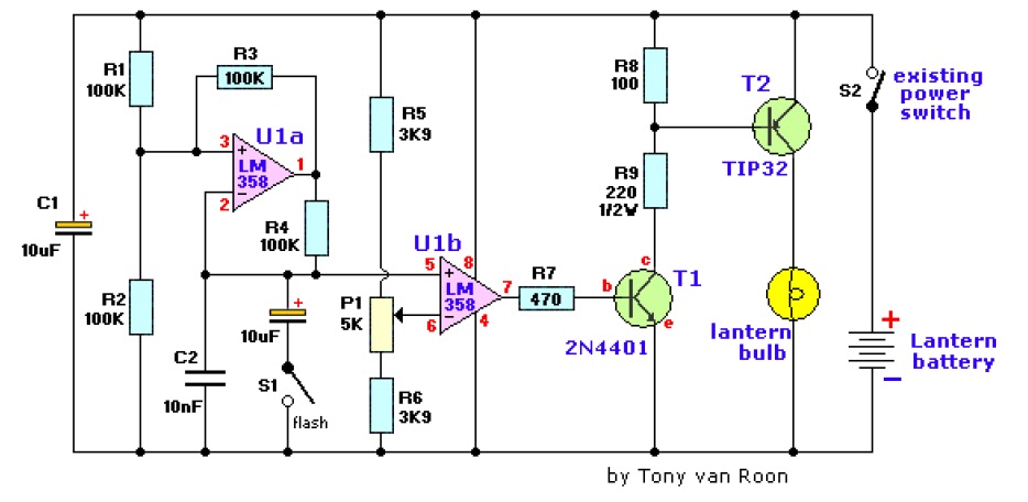
The electronic lantern control circuit enhances an existing battery-powered lantern or flashlight, or can be incorporated into a custom design, by providing high-efficiency dimming and flashing capabilities. This circuit is particularly useful in automotive applications, serving as an effective...
This is a simple light-running circuit synchronized with music. The circuit is straightforward, operating in mono, and requires only a few components. It can be connected to the output of a CD player. The described circuit utilizes a basic audio...
It is often necessary to configure a voltage regulator integrated circuit (IC) to provide a higher output voltage than that established by the regulator alone. One method to achieve this is by connecting the common terminal to the midpoint...
The Air Flow Sensor Circuit describes sensing air flow using the microcontroller PIC16C781. Air flow is detected by the cooling effect of air. The Air Flow Sensor Circuit utilizes the PIC16C781 microcontroller to effectively measure air flow by leveraging the...
Warning: include(partials/cookie-banner.php): Failed to open stream: Permission denied in /var/www/html/nextgr/view-circuit.php on line 713
Warning: include(): Failed opening 'partials/cookie-banner.php' for inclusion (include_path='.:/usr/share/php') in /var/www/html/nextgr/view-circuit.php on line 713