
Space Age Sound Machine Circuit
The 556 dual timer IC is a versatile component commonly used for generating precise timing and oscillation applications. In this circuit, the first timer is configured as an astable multivibrator, producing a continuous square wave output. The frequency of oscillation is determined by the resistor-capacitor (RC) network formed by K1, R2, and C1, which sets the timing interval for the high and low states of the output signal. The output at pin 5 is critical as it serves as the input to the second timer via the coupling network consisting of C2 and R5.
The second timer, also configured in astable mode, allows for frequency adjustment via P1, R6, and C3, enabling the user to modify the characteristics of the output sound. The integration of the two frequency outputs from the timers results in a complex waveform that produces the desired phasor effect, which is particularly appealing in sound design applications.
The amplified output from the second timer is routed through resistor R7 to control the base current of the PNP germanium transistor Q1. This transistor acts as a power amplifier, boosting the signal strength to a level capable of driving a speaker. The choice of a germanium transistor is significant due to its favorable characteristics for audio applications, including low distortion and high sensitivity.
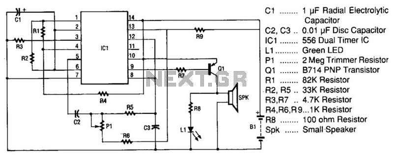
The inclusion of the green LED L1 adds a visual element to the sound output, providing an indication of the audio signal's activity. Resistor R8 is essential for protecting the LED from excessive current, ensuring longevity and reliable operation. The overall design of this circuit not only highlights the functional aspects of sound generation but also emphasizes the integration of visual feedback, making it suitable for various applications in electronic sound devices. The space-age sound device uses a 556 dual-times IC to produce a phasor sound. That IC is actually two 555 timer ICs in one 14-pin package, as shown in the schematic. Each timer inside the 556 is connected iri an astable multivibrator mode. The first timer has its frequency set by Kl, R2, and Cl. Its output appears on pin 5 and it is coupled through C2 and R5 into the trigger input of the second timer. The second timer has an adjustable frequency that is controlled by PI, R6, and C3. In the second timer, the first frequency mixes with the second frequency and produces the pha-sor-like sounds.
The output of the second timer, which has the two signals mixed together, is brought from pin 9 through limiting resistor R7 to the input of Ql. The function of pnp germanium power transistor Ql is to amplify the signal to the level that is needed to drive the speaker.
The green LED, LI, converts electrons directly into visible photons (light) in time with the pulses from the speaker. The purpose of resistor R8 is to limit the current through the LED to a safe level. 🔗 External reference
Related Circuits
This system is designed to communicate or transmit a text message from one location to another using a wireless circuit. The text message is encrypted with a microcontroller, and the encrypted message is transmitted wirelessly. At the receiving end,...

According to current legislation in many countries, vintage cars must also be fitted with a fog lamp at the rear. In modern cars, there is a bit of circuitry involved in the integration of fog lamps. Fog lamps are essential...
Understanding the concept of hysteresis is crucial. Generally, this phenomenon leads to losses observed in the dielectric of a capacitor or the lamination of a transformer, which can manifest as heat (emission of infrared photons). Alternatively, it can extract...
The range of this FM transmitter is approximately 100 meters when powered by a 9V DC supply. The circuit consists of three main stages. The first stage is a microphone preamplifier utilizing a BC548 transistor. The second stage features...
The circuit of the unit is fairly simple, but is a bit irksome to set up. The reason is that obtaining matched FETs is not easy, so I had to make sure that the circuit would work with off-the-shelf...
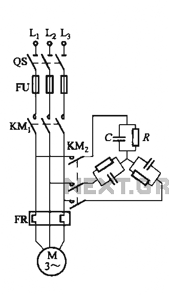
The circuit illustrated in Figure 3-151 consists of capacitor banks arranged in a specific configuration. Figure 3-151 (a) depicts capacitor banks connected in a shaped configuration, which is suitable for shaped or Y-connected motors. Figure 3-151 (b) shows Y-connected...