
Medium-Power FM Transmitter circuit
This FM transmitter circuit is designed to operate efficiently within a range of about 100 meters, making it suitable for various applications such as personal broadcasting or small-scale communication systems. The circuit is powered by a 9V DC supply, which is a common voltage for portable electronic devices.
The first stage, the microphone preamplifier, is crucial for amplifying the audio signals captured by the microphone. The BC548 transistor is selected for its low noise characteristics and ability to provide sufficient gain for the input audio signal. This stage ensures that the audio signal is adequately amplified before it enters the oscillator stage.
In the second stage, the VHF oscillator is responsible for generating the radio frequency signal. The oscillator circuit is designed to operate at a frequency suitable for FM transmission, typically within the VHF band. The use of the BC548 transistor in this stage capitalizes on its capability to function effectively as an oscillator, despite being primarily designed for low-frequency applications. The oscillator generates a carrier wave that modulates the audio signal from the preamplifier.
The third stage is a class-A tuned amplifier, which serves to amplify the modulated RF signal produced by the oscillator. This stage is critical for ensuring that the signal is strong enough to be transmitted over the desired distance. The class-A configuration is known for its linearity, making it ideal for audio applications where signal fidelity is paramount. The tuned circuit design allows for selective amplification of the desired frequency while attenuating unwanted frequencies.
To further enhance the transmission range, an additional RF amplifier can be integrated into the circuit. This amplifier increases the output power of the transmitter, allowing the signal to be transmitted over longer distances without significant loss of quality. The combination of these three stages—the microphone preamplifier, VHF oscillator, and class-A tuned amplifier—creates a robust FM transmitter circuit capable of delivering reliable performance within the specified range.The range of this FM transmitter is around 100 meters at 9V DC supply. The circuit comprises three stages. The first stage is a microphone preamplifier built around BC548 transistor. The next stage is a VHF oscillator wired around another BC548. (BC series transistors are generally used in low-frequency stages. But these also work fine in RF stages as oscillator.) The third stage is a class-A tuned amplifier that boosts signals from the oscillator. Use of the additional RF amplifier increases the range of the transmitter.. 🔗 External reference
Related Circuits
The example below illustrates the use of an operational amplifier (op-amp) as an audio amplifier in a basic intercom system. A small 8-ohm speaker is utilized as a microphone, which is connected to the op-amp input through a 0.1...
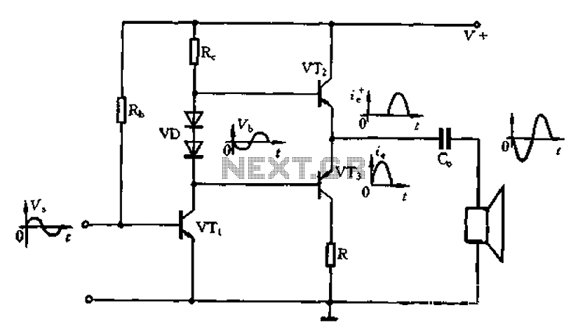
The Class A power amplifier exhibits low distortion; however, it suffers from low efficiency and limited output power, prompting the design of Class B power amplifier circuits. The Class B amplifier operates by shifting the operating point of the...
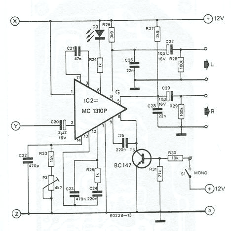
Based on Valvo FD-1A module, TBA120, and MC1310. Operation of the receiver is based on the phase locked loop principle. The FD-1A contains an RF amplifier, oscillator and mixer (made with BF324, BF451 and BF324 transistors, respectively). Tuning is...
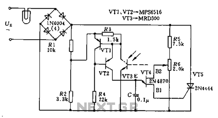
The circuit utilizes a thyristor-based AC automatic voltage regulator to stabilize the brightness of lamp L. A diagonal line connects the thyristor to the T5 bridge. The trigger pulse for the thyristor is generated by a single-junction transistor, VT4....

The core component of this digital volume controller (DVC) circuit is the IC2 4067, which is a 16-channel analog multiplexer. A 1kΩ resistor is connected between each input and output, allowing the multiplexer to function similarly to a potentiometer....
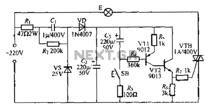
Another method employs a Zhu gall thyristor delay lamp circuit. Typically, a 220V AC supply is used, consisting of a step-down voltage half-wave rectifier circuit. The circuit outputs approximately 25V across the left and right terminals. At this point,...