
Speaker Protector Circuit
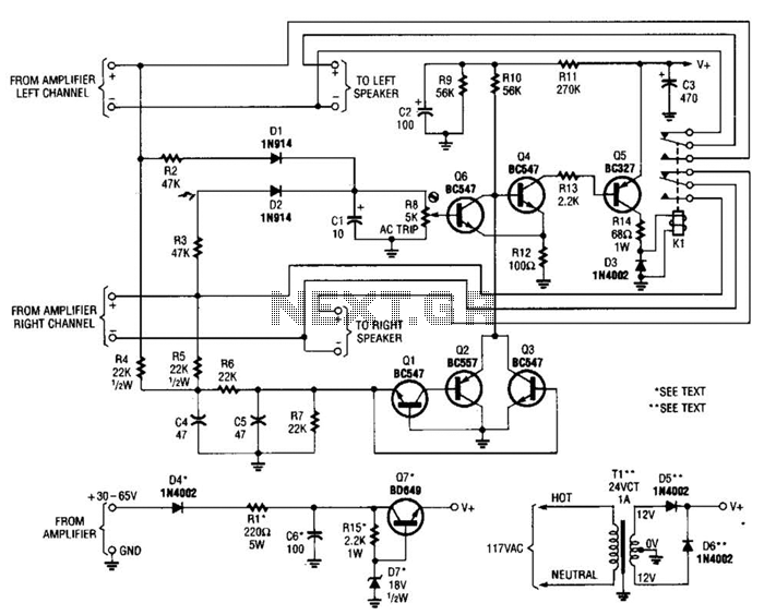
The speaker protector circuit is designed to safeguard speakers from potential damage caused by excessive DC voltage from the amplifier. The primary components involved in this protection mechanism include transistors Q1, Q2, Q3, Q4, and Q5, along with relay K1, and diodes D1, D2, and Q6.
In normal operation, Q4 and Q5 remain in the conducting state, which keeps K1 energized. This configuration allows the speakers to remain connected to the amplifier, ensuring proper audio output. The activation of Q4 is crucial, as it controls the state of Q5 and ultimately the relay K1.
When a large DC voltage is detected at the output of the amplifier, it triggers either Q3 or the combination of Q1 and Q2. The activation of these transistors biases Q4 into the off state. As Q4 turns off, Q5 also ceases to conduct, leading to the de-energization of relay K1. This disconnection is vital for protecting the speakers from the harmful effects of DC voltage, which can cause overheating and damage.
The overdrive protection circuit, formed by components D1, D2, and Q6, plays a critical role in monitoring the output voltage. Diodes D1 and D2 are typically configured to clamp the voltage levels, ensuring that any overvoltage conditions are detected promptly. Q6 serves as an additional control element that responds to the signals from the diodes, further enhancing the reliability of the protection circuit.
Overall, this speaker protection circuit is an essential component in audio amplification systems, ensuring that speakers are protected from damage due to overvoltage conditions while allowing for normal operation under safe conditions. The use of transistors and relays facilitates a quick response to potential threats, ensuring the longevity and performance of the audio equipment. Most of the transistors in this speaker protector function as switches. Normally, Q4, Q5, and K1 are on and the speakers are connected to the amplifier. However, if a large dc voltage appears at an amplifier output, either Q3, or Ql and Q2 turn on, biasing Q4 off. That action turns Q5 off, de-energizes the relay, and disconnects the speakers from the amplifier. Components Dl, D2, and Q6 form the overdrive-protection circuit. 🔗 External reference
Related Circuits
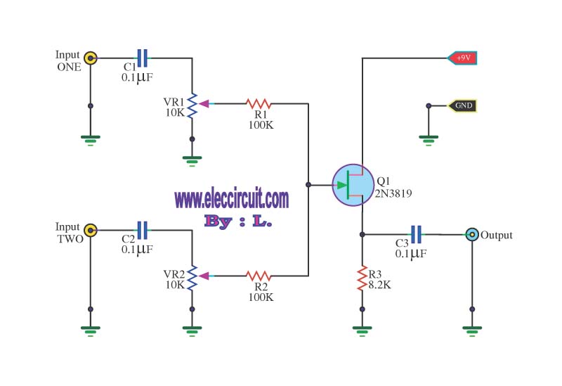
This circuit is a simple mixer circuit that can mix two signal channels into one output channel. It utilizes a codec circuit to convert stereo audio into mono audio. The circuit can also increase the number of channels by...
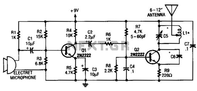
The vacuum tube remains relevant and functional in certain applications, such as in this continuous wave (CW) transmitter. The circuit is constructed in a traditional breadboard style on a wooden base. Old table radios serve as a valuable source...
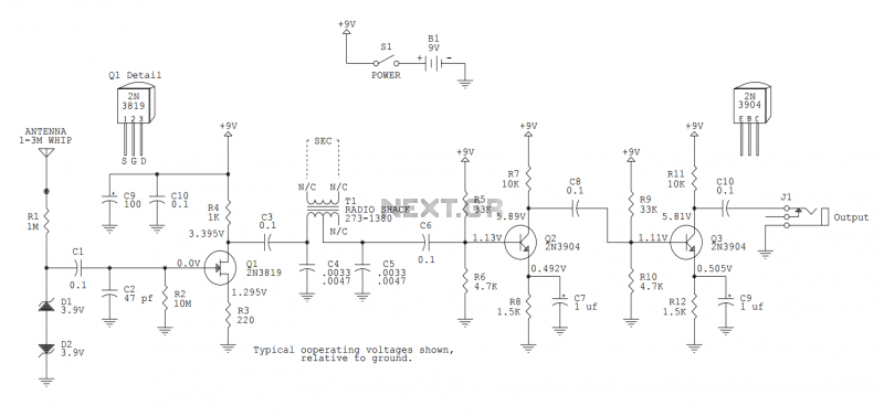
This version sports a 2nd audio amplifier stage at Q3. The output level with this version is sufficient to drive a crystal headphone to a comfortable volume. The "crystal" headphone is like those used on ye olde crystal radios....
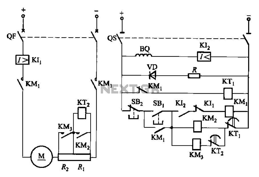
The circuit illustrated in Figure 3-191 features a DC motor armature circuit that includes two series startup resistors, Ri and Rz. The operation of the motor is controlled using buttons for starting and stopping. During the startup phase, two...
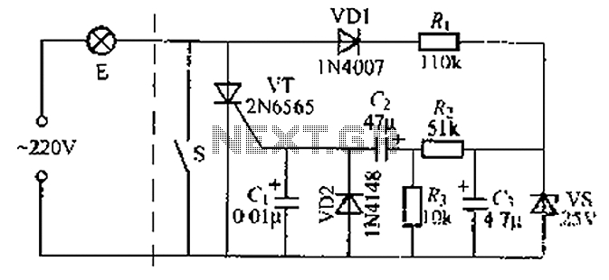
A delay circuit using an improved quenching lamp pull switch is described, focusing on its performance and the delay function in lighting control. The circuit exhibits a high degree of stability and reliability. When switch S is closed, the...
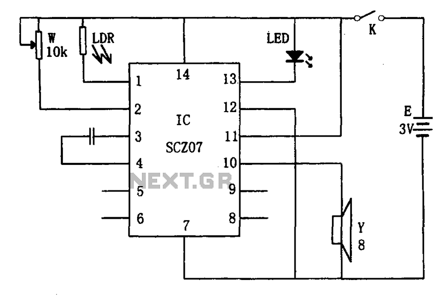
The weak light alarm circuit is illustrated in the figure. The oscillator circuit's core component is the SCZ07. The input signal is controlled by a potentiometer (W) and the output signal is processed by a photoresistor (LDR). The circuit...
Warning: include(partials/cookie-banner.php): Failed to open stream: Permission denied in /var/www/html/nextgr/view-circuit.php on line 713
Warning: include(): Failed opening 'partials/cookie-banner.php' for inclusion (include_path='.:/usr/share/php') in /var/www/html/nextgr/view-circuit.php on line 713