
Spectrum Analyzer Adapter for Oscilloscopes
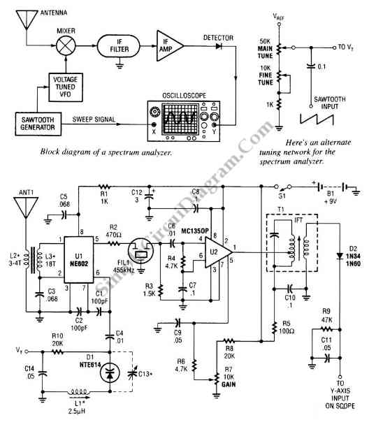
The spectrum analyzer adapter circuit is engineered to enhance the capabilities of an oscilloscope, allowing it to perform frequency analysis of input signals. The primary components of this circuit typically include resistors, capacitors, operational amplifiers, and possibly a microcontroller for signal processing and display.
The circuit operates by taking an input signal, which is then filtered through a series of bandpass filters. These filters are designed to isolate specific frequency ranges, enabling the oscilloscope to display the amplitude of signals within those ranges. Each filter stage contributes to the overall frequency response of the circuit, ensuring that only the desired frequencies are passed to the output.
Operational amplifiers are employed to amplify the filtered signals, providing sufficient gain for accurate display on the oscilloscope. The configuration of these amplifiers can be adjusted to accommodate various input signal levels, ensuring versatility in applications.
Additionally, the circuit may include a display interface, such as an LCD or LED array, to provide real-time visual feedback of the frequency analysis. This feature allows users to easily interpret the signal characteristics without needing to constantly refer to the oscilloscope screen.
Power supply considerations are also critical for the proper functioning of the spectrum analyzer adapter. A stable power source is necessary to maintain the integrity of the signal processing and avoid noise interference that could affect measurement accuracy.
Overall, this spectrum analyzer adapter circuit serves as a valuable tool for engineers and technicians, facilitating detailed analysis of signal frequencies and enhancing the functionality of standard oscilloscopes.The circuit shown in the following schematic diagram is a simple spectrum analyzer adapter circuit for oscilloscopes. This circuit can be used for scanning or.. 🔗 External reference
Related Circuits

The keypad circuitry is centered around a PIC1652 microcontroller manufactured by General Instruments. The PIC1652 is an 8-bit microcontroller featuring RISC-like characteristics and a 33 single-word instruction set. It supports various addressing modes, including direct, indirect, and relative addressing,...
Two photographs depict the interior of the NSN6054A. The metal brackets that secure the circuit board also serve as heat sinks for the 12-watt audio amplifier. The NSN6054A device features a robust design that integrates both mechanical support and thermal...
The Lazy Adapter is composed of a 20 pin DIP socket, a 20 pin DIP header, and a 6 pin ISP header, and a small phenolic circuit board to hold them all together. The green fiberglass PCB is a...
The capacitance between the wire and the probe would form a capacitive voltage divider with the probe's input capacitance, and at frequencies significantly higher than the low frequency roll off created by the probe's input capacitance and the probe's...

The car cigarette lighter outputs a DC voltage of 12 V, which does not exceed 13.8 V even when the engine is running. A voltage of 19 V is lower than the normally required levels. The car cigarette lighter circuit...
Dynamic flip-flops ignore pulses at their inputs that are shorter than 40 ns or do not have TTL levels. This means that TTL flip-flops are not well-suited for capturing noise pulses with unknown durations and magnitudes. This issue is...