
Spectrum 128 Keypad

The circuit design of the keypad system leverages the capabilities of the PIC1652 microcontroller effectively, allowing for robust communication and control of the keypad matrix. The microcontroller's architecture facilitates efficient processing of key inputs, while the inclusion of various components ensures the integrity and reliability of the operation. The use of zener diodes for voltage regulation protects the microcontroller from potentially damaging voltage levels, while resistors and capacitors are strategically employed to manage power-up sequences and signal integrity. The oscillator circuit is carefully designed to provide a stable clock frequency, which is crucial for the synchronous operation of the microcontroller. The physical design of the keypad, including the choice of materials for the matrix and the bubble mat, enhances user interaction by providing a responsive tactile feel. Overall, the integration of these elements results in a well-engineered keypad interface that aligns with the operational requirements of the Spectrum128 system.The keypad circuitry is based around a PIC1652 microcontroller that was manufactured by General Instruments. The PIC1652 is an 8-bit microcontroller with RISC-like features and has a 33 single-word instruction set.
It supports direct, indirect and relative addressing modes and features 7 special function hardware registers, 2 level deep stack, 12 I/O ports with individual direction control, an 8-bit real-time clock/counter with 8-bit programmable prescalar, power-on reset, power saving sleep mode and security fuse for code protection. It has 384x12 words of ROM and 25x8 bytes of RAM. It has a maximum operating frequency of 4MHz. The PIC microcontroller continually monitors the keypad matrix via lines RB3-RB7 and RA0-RA3. Lines RB3-RB7 select the row to read and the keys on this row will be read in via RA0-RA3. The keypad communicates to the Spectrum128 via RB0 and RB1. Line RB1 is the input from the Spectrum128 and the combination of resistor R3 and zener diode D1 converts the input voltages of +12V and -12V to +4.
7V and -0. 7V so that the PIC microcontroller can safely read in the line level. The output line to the Spectrum128 (RB0) is either at 0V or +5V and this is sufficient for the Spectrum 128 to read the line levels in as logic 1 and logic 0 respectively. Although +12V is supplied by the Spectrum128 to power the keypad, this is cut down to 5. 1V via zener diode D2. Resistor R4 and capacitor C1 cause a low pulse to line /MCLR at power up thus resetting the PIC microcontroller.
Resistor R1 separates the +12V power line from the 5. 1V dropped across zener diode D2. Resistor R3 performs a similar function separating the +12V or -12V from the 4. 7V or -0. 7V dropped across zener diode D1. Resistor R2 limits the current drawn from the output line in case of a short circuit. Inductor L1 and capacitors C2 and C3 form the oscillator that clocks the microcontroller and have values 68 µH, 47pF and 47pF respectively. The keypad circuit diagram is shown below. where C is the series capacitance of the capacitors C2 and C3 plus the parallel capacitances of the OSC1 and OSC2 pins of the PIC.
These are 4pF and 4. 3pF with a part tolerance of 25%. This yields a nominal frequency of 3. 422568MHz but when the tolerances are taken into account this can range from 3. 057491MHz to 3. 888368MHz. The keypad is held together by six screws. Inside the keypad is the printed circuit board (P. C. B. ), the keypad matrix and the bubble mat which provides the `spring` feedback of the keys. The cable to the P. C. B. consists of four wires coloured blue, white, red and green, as shown above. The plug pins are coloured as per the socket pins in the Spectrum128 and these are shown in the section entitled Communication Details. The matrix is constructed of clear plastic which seems to be typical of the keyboard membranes found in non-UK models of the Spectrum, and these tend to be more robust than the UK versions.
The P. C. B. inside the keypad measures 38mm wide x 40mm high and is double sided. The PIC microcontroller is soldered directly onto the printed circuit board. The PIC is labelled `PIC1652-441 KP27C85SRL GI8534YTAIWAN`. 🔗 External reference
Related Circuits

The CP2128 is a low-noise, fixed-frequency step-up DC/DC converter designed for garden applications. It operates within an input voltage range of 2.7V to 4.5V and can generate a stable output voltage of 5V, with a maximum output current of...
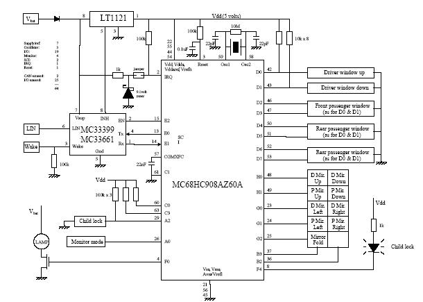
A car door differs from a calculator or a phone in that it makes sense to press more than one key at a time. The functionality of a car door can be compared to that of a multi-key input device,...

This is a simplified version of the Universal Keypad-Operated Switch. The design has been modified to reduce circuit complexity and the number of components required. As a result, the code is somewhat less secure; however, it remains adequate for...
The circuit shown in Figure 1 uses only two ICs, and has a bandwidth that is adjustable from more than one octave down to a tenth of an octave. As shown, the frequency range is 20 Hz. to 20...
The integrated circuit (IC) is a quad 2-input "AND" gate, specifically a CMOS 4081. These gates output a HIGH signal only when both inputs are HIGH. When the key connected to pin E is pressed, current flows through resistor...
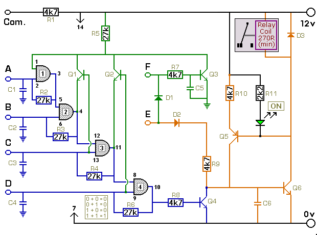
The key connected to "E" is used to energize the relay, while the four keys connected to A, B, C, and D are used to de-energize it. All other keys on the keypad are connected to "F". When "E"...