
Lazy ISP Socket Adapter
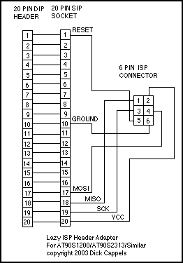
More: The writing is simple: pins on the 20 pin socket are soldered to the corresponding pins on the 20 pin header. The six pins of the ISP header, as identified in the AVR910 application note from Atmel, are wired to the corresponding pins on the 20 pin socket, as identified by the AT90S2313 datasheet. Wiring for the 20 pin adapter. The wiring for the 8 pin adapter is similar, though the pin numbers are different. Below is a wiring diagram showing the adapter for the 20 pin AVR processors.
The Lazy Adapter is designed to facilitate the connection of AVR microcontrollers to programming and debugging tools without the need for repetitive wiring tasks. The primary components include a 20-pin Dual In-line Package (DIP) socket, a 20-pin DIP header, and a 6-pin In-System Programming (ISP) header, all mounted on a compact phenolic circuit board. The circuit board is made of green fiberglass, specifically a Dontronics DT104 SIMSTIC, which is known for its durability and reliability in prototyping applications.
The 20-pin DIP socket is intended to connect directly to an AVR microcontroller on a breadboard. This allows for easy insertion and removal of the microcontroller while maintaining a secure connection. The 20-pin DIP header serves as a pass-through connection, where each pin is carefully soldered to its corresponding pin on the DIP socket, ensuring that all signals and power connections are preserved.
The 6-pin ISP header is configured according to the standard layout used in Atmel's STK-500 programming kit, which simplifies the programming process. The wiring for the ISP header is based on the AVR910 application note, which provides pin assignments for programming various AVR microcontrollers. The wiring scheme connects the six ISP pins to specific pins on the 20-pin socket, as detailed in the AT90S2313 datasheet. This arrangement allows for seamless programming and debugging of the microcontroller without occupying additional space on the prototype board.
In addition to the 20-pin adapter, an 8-pin version has been developed for the ATTiny12 microcontroller. The wiring for this adapter is similar to that of the 20-pin version, although the pin assignments differ. A wiring diagram is typically provided to illustrate the connections for both the 20-pin and 8-pin adapters, ensuring clarity and ease of use for the designer. Overall, the Lazy Adapter is an efficient solution for streamlining the development process of AVR-based projects.The Lazy Adapter is composed of a 20 pin DIP socket, a 20 pin DIP header, and 6 pin ISP header, and a small phenolic circuit board to hold them all together. The green fiberglass PCB is a Dontronics DT104 SIMSTIC(This plug is in return for a favor.) I am tired of wiring up ISP sockets for every little breadboard I build, so I built this little adapter.
It plugs into a 20 pin IC socket for an AVR on a breadboard. On the adapter is the 6 pin ISP header in the same configuration used on the STK-500. Besides saving me time, it also means I don't have to make room on the prototype for the ISP header. I've also made an 8 pin version for the ATTiny12. The writing is simple: pins on the 20 pin socket are soldered to the corresponding pins on the 20 pin header. The six pins of the ISP header, as identified in the AVR910 application note from Atmel, are wired to the corresponding pins on the 20 pin socket, as identified by the AT90S2313 datasheet.
Wiring for the 20 pin adapter. The wiring for the 8 pin adapter is similar, though the pin numbers are different. Below is a wiring diagram showing the adapter for the 20 pin AVR processors. 🔗 External reference
Related Circuits
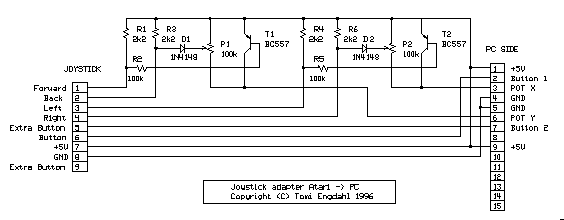
Some games are easier to play with a digital joystick instead of an analogue type. Unfortunately, PC has only an analogue joystick connector, which makes it impossible to connect a normal digital joystick to it. But with a little...
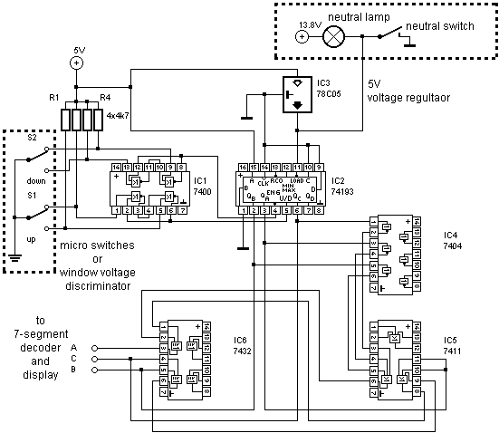
A universal digital gear display that can be installed on any motorbike. This is a low-cost solution based on simple TTL digital technology without software programming. The universal digital gear display is designed for easy installation on a variety of...
A brief history: Like many tutorials, this one begins with a historical overview. However, it must be noted that there is limited background information available regarding the development of 7-segment displays. 7-segment displays are widely used electronic components that...
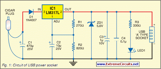
Nearly all modern computers are equipped with logic blocks that facilitate the implementation of a USB port. A USB port can deliver over 100 mA of continuous current at 5V to peripherals connected to the bus. Therefore, it serves...
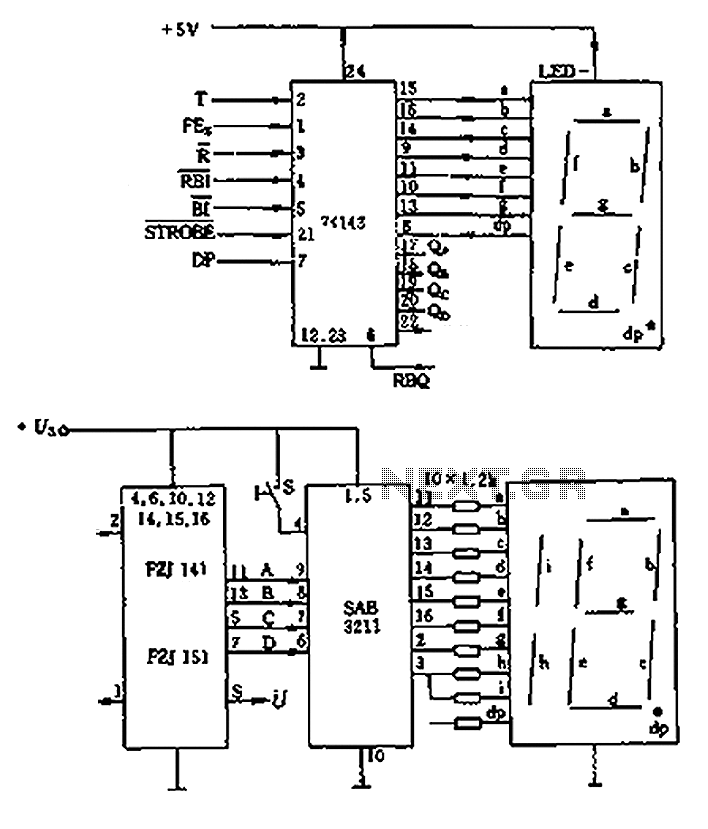
The decimal seven-segment storage decoding drive unit 74HC143 provides a constant output for all segments, each at a voltage of 5V and a current ranging from approximately 15mA to 22mA. The BCD data for the seven-segment decoder can be...

The digital display temperature detection circuit utilizes a precision digital display to indicate temperature readings. The circuit employs the MC1403, which outputs a reference voltage, with the potentiometer RP5 setting the reference value for the inverting terminal (a) of...