
Wiper Speed Control With NE555 IC
The Wiper Speed Control Circuit is designed to regulate the speed of windshield wipers in vehicles, enhancing driver visibility and safety under varying weather conditions. The circuit typically consists of a timer, a variable resistor (potentiometer), and a relay or transistor that controls the power supplied to the wiper motor.
At the core of the circuit is a timer IC, such as the NE555, configured in astable mode. This setup allows the timer to produce a square wave output that can be adjusted by changing the resistance value of the potentiometer. The frequency of this square wave determines the interval between wiper sweeps. By adjusting the potentiometer, the user can set the wiper speed anywhere from one sweep per second to one sweep every ten seconds, providing flexibility based on the intensity of the rain or other environmental conditions.
The output from the timer is fed into a relay or a transistor, which acts as a switch to control the power to the wiper motor. When the timer output goes high, the relay closes, allowing current to flow to the wiper motor, causing it to operate. When the output goes low, the relay opens, cutting off power to the motor and stopping the wiper.
Additional components may include diodes for flyback protection across the relay coil, capacitors to stabilize the power supply, and resistors to limit current where necessary. The entire circuit can be powered by the vehicle's battery, typically at 12V, ensuring compatibility with standard automotive electrical systems. This circuit design not only improves the functionality of wipers but also contributes to the overall safety and comfort of driving in adverse weather conditions.This circuit shows a Wiper Speed Control Circuit Diagram. Sweeping rate of the wiper can varying from once a second to once in ten seconds. This .. 🔗 External reference
Related Circuits
The 0.1µF monolithic capacitors will be marked '103 K' and the 15pF monolithic capacitors are marked '15 J'. It is crucial not to confuse the two. Do not remove either the MOSFETs or the integrated circuits from their protective...
This simple microcontroller circuit regulates a servo motor based on a 3-state switch. The servo motor functions as an actuator with three positions. It consists of three wires: one for VCC, one for ground, and a third for position...
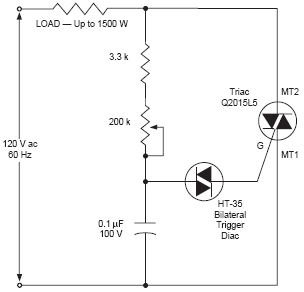
The DIAC, or diode for alternating current, is a trigger diode that conducts current only after its breakdown voltage has been momentarily exceeded. Most DIACs are utilized in applications requiring a switching function in AC circuits. The DIAC is a...
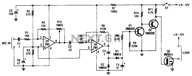
The audio-controlled switch utilizes a pair of 741 operational amplifiers, two 2N2222 general-purpose transistors, a hexFET, and several supporting components to create a circuit capable of activating devices such as a tape recorder, a transmitter, or virtually any other...
This weblog discusses electronic circuit schematics, PCB design, DIY kits, and electronic project diagrams. The rain detector operates on the principle of an astable multivibrator using the 555 timer IC, which is equipped with a sensor capable of detecting...
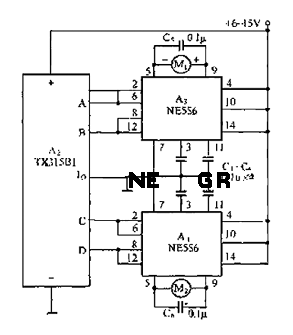
The travel remote control model is represented by a circuit diagram. The NE556 is a dual time base IC that includes two separate circuits, each consisting of a Schmitt trigger circuit. The output control is achieved through the TX315B1,...