
Speed-limit Alert
This circuit operates based on the principle of monitoring engine RPM to provide a non-intrusive alert system for the driver. The differential amplifier formed by IC1 is crucial for capturing the electromagnetic pulses generated by the engine's spark plugs. The sensor coil L1 is strategically placed to ensure optimal sensitivity to these pulses. The amplified signals are then processed by a series of inverters (IC2B to IC2F), ensuring that the pulses are squared for reliable detection.
The monostable multivibrator IC3A plays a vital role in establishing a threshold for the speed limit detection. When the vehicle reaches the predetermined speed, the output at pin 6 goes high, triggering the alert system. The combination of the beeper and LED D5 provides both audible and visual feedback, enhancing the driver's awareness of speed limits.
The circuit's design allows for easy calibration through the use of trimmer resistors, which enable fine-tuning of the response to the vehicle's speed. The option to bypass certain components after calibration ensures that the circuit remains efficient and conserves battery power when not in use. The use of a compact inductor for the sensor coil allows for easy integration into the vehicle's dashboard or nearby areas, maintaining a clean and unobtrusive installation.
Overall, this speed alert circuit is an effective solution for enhancing driver safety by reducing distractions associated with monitoring speed through traditional instruments. It combines simplicity in design with effective functionality, making it suitable for a wide range of vehicles.This circuit has been designed to alert the vehicle driver that he has reached the maximum fixed speed limit (i. e. in a motorway). It eliminates the necessity of looking at the tachometer and to be distracted from driving. There is a strict relation between engine`s RPM and vehicle speed, so this device controls RPM, starting to beep and flashing
a LED once per second, when maximum fixed speed is reached. Its outstanding feature lies in the fact that no connection is required from circuit to engine. IC1 forms a differential amplifier for the electromagnetic pulses generated by the engine sparking-plugs, picked-up by sensor coil L1. IC2A further amplifies the pulses and IC2B to IC2F inverters provide clean pulse squaring. The monostable multivibrator IC3A is used as a frequency discriminator, its pin 6 going firmly high when speed limit (settled by R11) is reached.
IC3B, the transistors and associate components provide timings for the signaling part, formed by LED D5 and piezo sounder BZ1. D3 introduces a small amount of hysteresis. * D1 is necessary at set-up to monitor the sparking-plugs emission, thus permitting to find easily the best placement for the device on the dashboard or close to it.
After the setting is done, D1 & R9 can be omitted or switched-off, with battery saving. * During the preceding operation R8 must be adjusted for better results. The best setting of this trimmer is usually obtained when its value lies between 10 and 20K. * The final simplest setting can be made with the help of a second person. Drive the vehicle and reach the speed needed. The helper must adjust the trimmer R11 until the device operates the beeper and D5. Reducing car`s speed the beep must stop. * L1 can be a 10mH small inductor usually sold in the form of a tiny rectangular plastic box. If you need an higher sensitivity you can build a special coil, winding 130 to 150 turns of 0. 2 mm. enameled wire on a 5 cm. diameter former (e. g. a can). Extract the coil from the former and tape it with insulating tape making thus a stand-alone coil. * Circuit`s current drawing is approx. 10mA. If you intend to use the car`s 12V battery, you can connect the device to the lighter socket. In this case R20 must be 330R. * Temporarily disconnect C2 from IC1`s pin 6. Connect the generator`s output to C2 and Ground. Set the generator`s frequency to i. e. 100Hz and regulate R11 until you hear the beeps and LED D5 flashes. Reducing the frequency to 99 or 98 Hz, beeping and flashing must stop. 🔗 External reference
Related Circuits
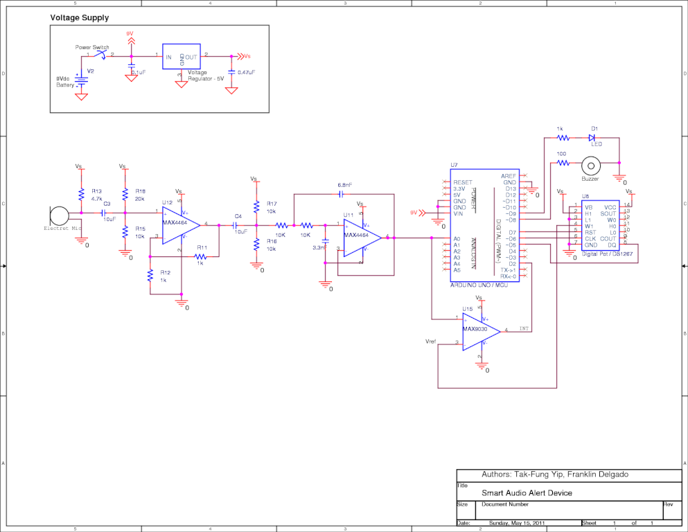
This is a senior project from Stony Brook University, designed and implemented by Tak-Fung Yip and Franklin Delgado, with consultation from Professor Milutin Stanac. The senior project from Stony Brook University represents a collaborative effort in the field of electronics...
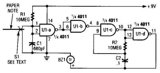
This device prevents paper notes and memos from being overlooked. A paper note placed between two fingers made of a conducting material (metal or conductive plastic) breaks the circuit, allowing pair 1 of Ul-a to go high. The goal...
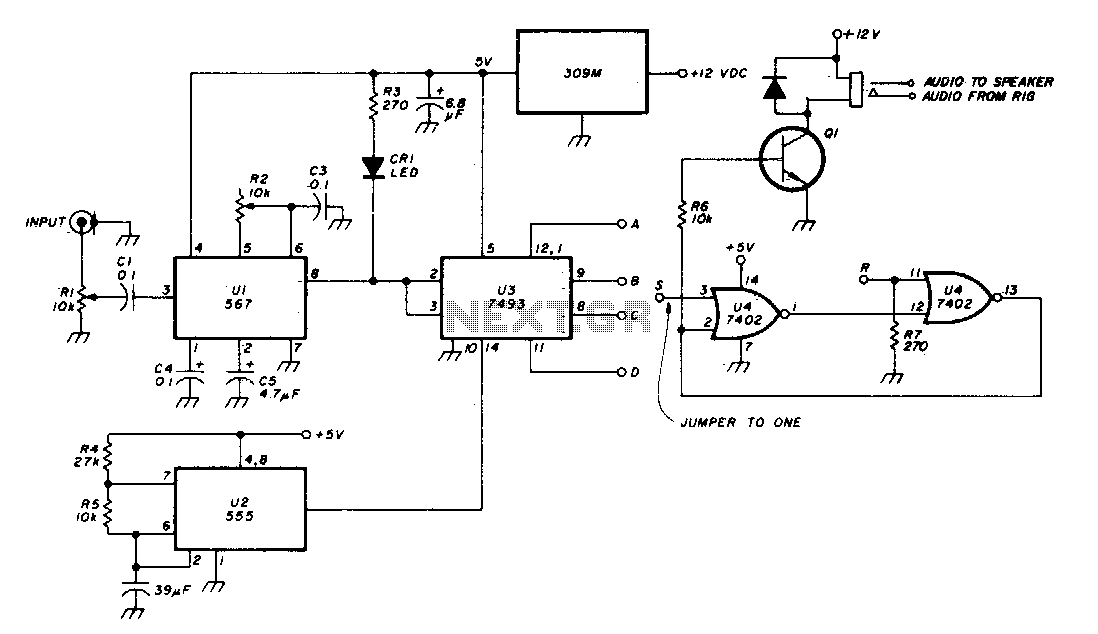
The Phase-Locked Loop (PLL) integrated circuit (U1) is configured with resistor R2 to achieve the desired tone frequency. An LED indicator is used to show when the PLL has locked onto the signal. To ensure proper lock-up, the signal...
The following circuit illustrates a Mains Remote-Alert Circuit Diagram. Features include simple circuitry, with the transmitted signal being conveyed effectively. The Mains Remote-Alert Circuit is designed to provide a notification system that alerts users about the status of mains power....
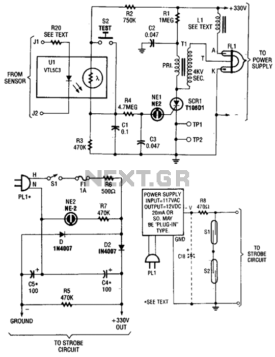
The circuit is activated by an LED/photoresistor isolator (U1), which combines a light-dependent resistor (LDR) and an LED in a single package. This device was selected for its high isolation characteristic of 2000 V, which is essential since the...

This circuit has been designed to alert the vehicle driver that he/she has reached the maximum fixed speed limit (i.e. in a motorway). It eliminates the necessity of looking at the tachometer and to be distracted from driving. There...