
Speed of Light with an IR LED
The circuit design for this speed of light measurement system encompasses several key components. The infrared LED (TSFF5210) is driven by the avalanche transistor (2N2369A) pulser circuit, which is configured to deliver high peak currents in short bursts, ensuring the generation of sharp optical pulses. The photodiode (BPV10) is strategically placed to capture the light from both paths effectively. The non-inverting AD8001 operational amplifier is critical for signal amplification, providing necessary gain while maintaining signal integrity. The optical paths are meticulously designed, with lenses selected based on their focal lengths to optimize the collection and focusing of the light onto the photodiode. The use of a beamsplitter allows for the simultaneous measurement of both the direct and delayed optical pulses, enabling precise timing measurements crucial for calculating the speed of light. The oscilloscope serves as the final component, capturing and displaying the electrical signals generated by the photodiode, allowing for analysis and measurement of the time delay between the two pulses. This experimental setup is designed to minimize noise and maximize the clarity of the detected pulses, facilitating accurate measurements of the speed of light.The speed of light has been measured many different ways using many ingenious methods. The following note describes a method which is conceptually easy to understand and fairly easy to implement. The technique is the simple time-of-flight optical pulse delay method using a short (20 nanosecond) intense infrared LED optical pulse, a high speed phot
odiode and preamplifier and an oscilloscope with a bandwidth between 50 - 100 MHz. The light from the LED passes through a beamsplitter (BS) close to the source. The reflected light from the beamsplitter (path L0) is focused onto the photodiode (Pd). The light that passes throught the beamsplitter (path L1 = L1a + L1b) travels a much longer path to a mirror and is reflected and focused using a different lens onto the same photodiode. If the path difference (L1 - L0) is long enough and the LED optical pulse is short enough, the optical pulses focused onto the photodiode will not overlap in time.
A measurement of the path difference (L1 - L0) and the measured time difference of the electrical pulses from the photodiode receiver circuit allow for an easy determination of the free space speed of light. With careful length measurements, a modest accuracy of about 1% is achievable: A high-speed and intense infrared LED is most convenient for the optical measurement.
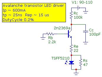
High speed means that shorter optical pulses can be created facilitating shorter delay paths. High intensity means that optical alignment and focusing is easier. A Vishay 870 nm IR LED (TSFF5210) was chosen with a bandwidth of 25 MHz with tr/tf ~ 15ns. A high speed high current avalanche transistor (2n2369a) pulser circuit was used to drive the LED with 25 ns 600 mA peak current pulses with a duty cycle of 0. 2% which is within the specifications for this LED. The schematic diagram and compact circuit board for the IR LED pulse source is shown below: A Vishay BPV10 high speed Si pin photodiode with a bandwidth of 200 MHz was used to detect the light pulses.
The photodiode was reverse biased at 15V to increase speed and lower capacitance. An AD8001 op amp preamplifier in a noninverting configuration with a gain of 35 (31 dB) and BW of 50 MHz was use to amplify the photodiode signal. The input termination resistance of 50 ohm combined with this gain is equivalent to a transimpedance of 1.
75 kohm. It is important to optimize the optical collection since an LED source is not well collimated. Using good lens focusing and collimation is essentially "noiseless" gain. The noise level of higher-gain preamplifiers will reduce the ability to detect weak signals particularly over long optical delay paths. In the current setup the LED output was collimated with a lense of f = 300 mm and diam=4" as shown below.
The light from path L0 was focused onto the photodiode with a f=75mm lens and light from path L1 was focused with a f=125mm lens of comparable thickness as shown below: The optical pulse from the beamsplitter path (L0) is shown below (the L1 path was optically blocked). The pulse width is approximately 30ns in duration. The pulse fall time is about 12 ns, limited by the LED response time and consistent with its 25 MHz bandwidth.
It was verified that the photodiode and preamplifier circuit combination operated well within the linearity limits : To ensure that the delayed optical pulse did not overlap in time with the "tail" of the beamsplit pulse, a delay time of at least 40ns was required and therefore a delay time of about 60 ns was chosen (corresponding roughly to a 60 ft path difference). The image below shows both the beamsplit and delayed pulses, showing a very clean separation of the two optical pulses.
The beamsplitter was adjusted to ensure that both received optical pulses were of comparable amplitude to minimize any possible source of intensity dependence of pulse shape. As can be seen, the two pulses are virtually identical. Although the oscilloscope has a band 🔗 External reference
Related Circuits
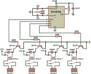
This is a relay driver based on a PIC16F84A microcontroller. The board includes four relays, allowing control of four distinct outputs. The relay driver circuit utilizing the PIC16F84A microcontroller is designed for controlling multiple devices or systems through relay activation....
I decided to make a commercial surface mount PC board using the LED2 sensor concept. It is quite sensitive and can track to a few degrees of accuracy in bright sunlight. If a blocking shadow is used the accuracy...
This project involves creating an RGB LED-lit love heart controlled by a PIC12F683 microcontroller. The design serves as a gift for a 15th wedding anniversary. The heart is crafted from a 200x150x6mm sheet of plexiglass, which is cut and...
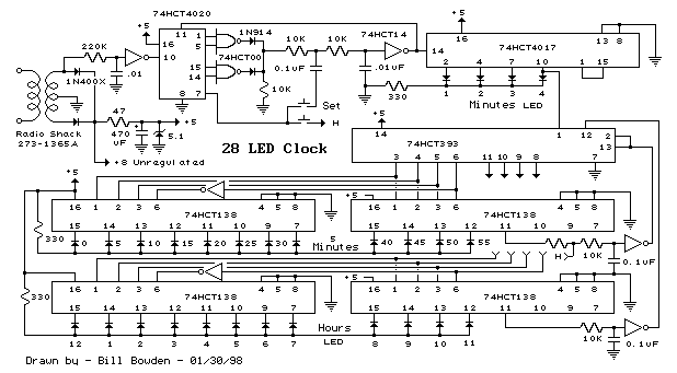
This is a programmable clock timer circuit that utilizes individual LEDs to display hours and minutes. Twelve LEDs can be arranged in a circular pattern to represent the 12 hours on a clock face, while an additional 12 LEDs...
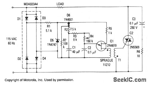
The Zener diode provides a constant voltage of 20 V to the unijunction transistor Q1, except at the end of each half-cycle of the input when the line voltage drops to zero. Initially, the voltage across capacitor C1 is...
The title contains numerous words because this instructable integrates various concepts from multiple sources. The primary idea originated from Robomaniac's Desktop Energy Seed Lamp, combined with Witch's Growing Plants with LED Lights instructable and various wick gardening planters. The...