
Speed regulator for dc motors
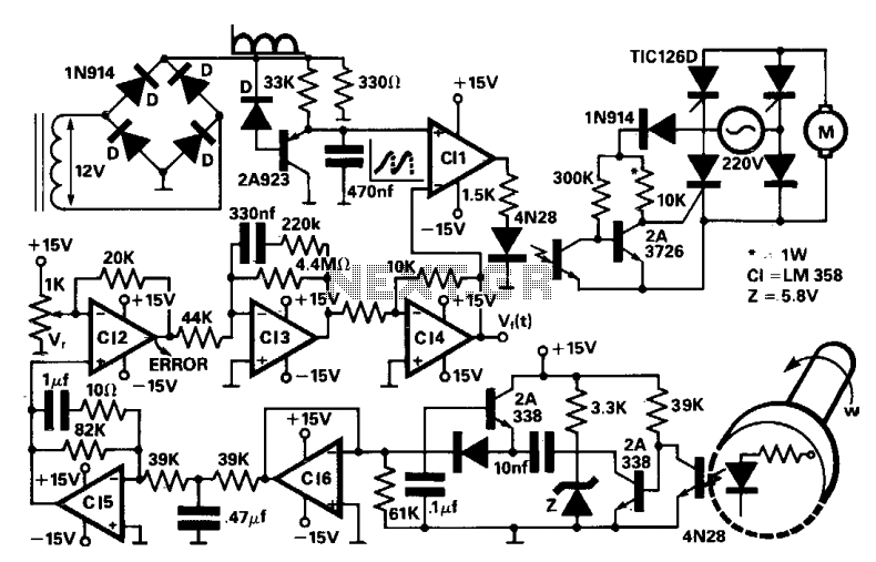
The described circuit employs a four thyristor controlled bridge configuration, which is adept at managing bidirectional power flow and is suitable for applications requiring control in both forward and reverse directions of torque. This capability is crucial in various industrial motor control applications, allowing for efficient operation in two quadrants of the torque-speed curve, specifically the motoring and regenerative braking modes.
The innovative use of self-biased circuits in the trigger section replaces traditional pulse transformers, thereby minimizing the power drawn from the gate and enhancing the overall efficiency of the system. This design choice not only reduces power consumption but also improves noise immunity, which is vital in environments where electromagnetic interference could affect performance.
The incorporation of optocouplers provides electrical isolation between the control side and the power side of the circuit, ensuring that high voltages do not affect the sensitive control circuitry. This isolation is critical for maintaining the integrity and safety of the control signals, particularly in high-power applications.
Trigger pulses are generated through a comparison mechanism that involves an error signal derived from the difference between the actual speed of the motor and a reference speed signal. This error signal is first amplified and processed to ensure that it is suitable for triggering the thyristors. The line synchronism signal serves as a timing reference, enabling precise control of the thyristors in relation to the AC supply, which is essential for maintaining the desired output characteristics.
The output of the converter is a DC voltage that is directly proportional to the motor speed, facilitating smooth and efficient control over the motor's operation. By continuously comparing this output with a reference signal, the system can dynamically adjust the firing angles of the thyristors, thereby regulating the speed and torque as required by the application. This feedback mechanism ensures that the motor operates optimally under varying load conditions, enhancing performance and reliability.A four thyristor controlled bridge is used for operation in two quadrants of the torque-speed characteristics. In the trigger circuits the usual pulse transformers were replaced by self biased circuits which minimize gate power consumption and increase noise immunity.
Electrical isolation is guaranteed by the use of optocouplers. The trigger pulses are generated by the comparison between an error signal, previously processed and amplified, and a line synchronism signal. The converter's output is a dc voltage proportional to the speed, which after being compared with a reference signal, becomes the error signal. 🔗 External reference
Related Circuits
Before designing an adjustable voltage regulator into a circuit or performing a redesign, it is essential to calculate the values for two resistors. While this calculation is straightforward, locating the appropriate resistors may present challenges. Fortunately, a technique exists...

The LA9472A is a 2A monolithic step down switching regulator operating in continuous mode and realized in a new BCD technology allowing the integration of isolated, vertical DMOS power transistors with mixed CMOS/bipolar transistors. The device can deliver 2A...
If an AC fan has three buttons (as in this case), button 1 is for low speed, button 2 is for half speed, and button 3 is for high speed. A relay can be used to switch between these...
This document outlines the theory behind a high-speed control scheme for an LED display screen circuit. The circuit utilizes the MCS51 series microcontroller to manage the LED display. A 62512 random access memory (RAM) is employed for data storage,...
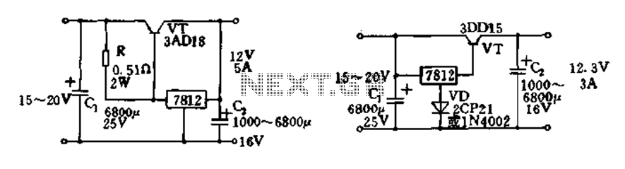
Expand integrated three-terminal regulator block circuit output current method The integrated three-terminal regulator is a versatile component commonly used in power supply circuits to provide a stable output voltage. This regulator typically consists of three terminals: input, output, and ground....
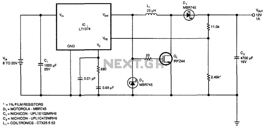
This regulator provides 12 V at 1 A output with an input voltage range of 8 to 20 V. The output voltage can be adjusted by changing the values of the resistors ll-kii and 2.49 kΩ to achieve 2.21...