
speedometer project

The design of the infrared LED speedometer circuit emphasizes simplicity and cost-effectiveness while providing accurate speed measurements. The integration of the 555 timer ICs for both modulation and timing functions streamlines the design, making it accessible for hobbyists and educational projects. The use of an IR LED and detector capitalizes on existing technology from remote control systems, ensuring reliability and performance without the need for complex optical systems.
The calibration process is straightforward, allowing users to adjust the system to provide accurate readings in either mph or kph based on the specific application. The incorporation of a data logger facilitates ongoing speed monitoring, making the device suitable for various activities, including recreational longboarding or commuting.
This project not only serves as a practical application of physics and engineering principles but also encourages experimentation and innovation in the field of instrumentation. By using common components and providing detailed instructions, the project is designed to be approachable for individuals with varying levels of experience in electronics, making it an excellent educational tool for aspiring physicists and engineers.A simple low cost Infrared LED speedometer is described that can be fitted to a skateboard, longboard or even a bicycle to measure speed. Notes on building, setting-up and calibration are given. When used with a low cost data logger continuous measurements of speed can be made while out-and-about.
The device forms an interesting science club project and would be a great introduction to potential physicists and engineers to scientific instrument design, testing and calibration as well as to generate lots of their own interesting data to analyse. Fig. 1. Longboard skateboard with IR speedometer circuit attached underneath the board. The electronics is housed in the small di-cast box under the board (right). Skateboarding has been around for at least 60 years but in its popular form since the seventies [1]. Recently longboarding has started to become popular with adults as well as with children [1]. The longboard has larger wheels and wider trucks than skateboards making it more stable for adults as well as better equipped for commuting and long trips.
YouTube videos show that people are now using longboards on 2000 km treks! [2]. As longboards are generally better made and larger than skateboard they are easier structures on which to develop instrumentation and measurement equipment. It`s great fun to combine science, instrumentation and longboarding. Here we use Infrared (IR) light to monitor the speed of rotation of one of the wheels. Light from an IR LED is directed at one of the wheels. The wheel has a small reflector fixed to it (see below) and when it rotates into position it reflects a signal back to an IR receiver.
On reception of the IR beam the receiver o/p pulses low (0V) for a short period. These pulses are too variable to monitor directly but we use them to trigger a timer (555 No. 2) which produces pulses of regular duration (ca. 15 ms, see below). These positive going pulses are then averaged using a simple low pass filter / integrator circuit (Ri and Ci) which smoothes the pulses creating a DC voltage proportional to speed. Data Logging allows measurements to be made out-and-about. A simple constant calibration (K) allows the voltage data to be converted into mph or kph etc. The transmitter circuit consists of an astable oscillator (555 No. 1) which pulses (modulates) the IR LED at 38 kHz. We use a standard IR LED as used in remote control systems (e. g. TV, cd, cable etc. ). A cheap commercially available IR detector (as used in TV remote control systems) is used (Note: we are using this device out-of-spec but its use greatly reduces the components needed).
These are sensitive to IR modulated at 38 kHz (hence the Tx frequency). Although these devices are very cheap they have built-in filters and tuned pre-amps to give good stability and sensitivity. We make use of this reliable remote control spin-off technology which provides much better noise immunity than a visible light beam circuit.
The circuit involves a straight forward use of the ubiquitous 555 timer. I used two separate 555 for my prototypes, to help in fault finding, but a double 556 timer could be used for compactness. All the components are cheap and easy to obtain. None of the components are very critical but good quality components should be used for the timing capacitors (e.
g. use metallised polyester for the 1nF and 0. 22uF capacitors). The total cost of the electronic components should be about 10 pounds / Euros. You might even be able to take an old cd or TV and controller apart to use both the IR transmitter LED and detector IC etc. Note: A specialised frequency-to-voltage (e. g. LM331) or techometer (e. g. LM2917) IC could have been used instead of the second 555 timer. This would probably produce a more linear and wider 🔗 External reference
Related Circuits
This circuit is a digital radar speedometer that measures the speed of moving objects, particularly vehicles such as cars. The speed is displayed in kilometers per hour (KPH) using a three-digit display. The radar operates on the principle of...
This simple telephone switching system is designed by Dr. Mustafa Kemal Peker for training purposes. All responsibility belongs to the user. Schematic and circuit details are included. The telephone switching system designed for training purposes serves as an educational tool...
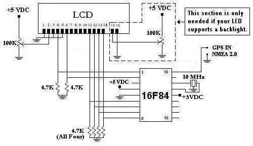
This is a project that I started back late 2003 when I just starting to learn PIC programming. I wanted to building something that actually did something useful. This project is based on a PIC16F84. I actually came up...
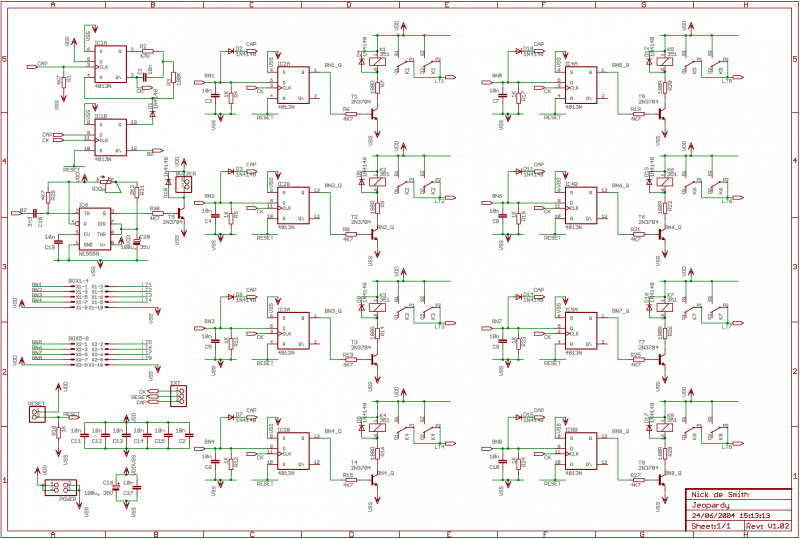
If 12V relays are used, you can replace the 180R resistors R7, R9, R14, R16, R20, R22, R26, and R28 with a wire link (the resistors are only there to limit current if you use 5V relays, of which...
The microcontroller board is displayed (top left/green board) alongside the auxiliary board (bottom left/brown board) and two geared Hurst stepper motors. In this view, the programming jumper is located in the upper right area of the microcontroller board, while...
This circuit was inspired by a friend who wanted a reverb for his portable guitar amplifier. I originally tried using NE5532 low noise op-amps for the buffer stages but they were too noisy for the low level circuits so...