
Digital Radar Speedometer
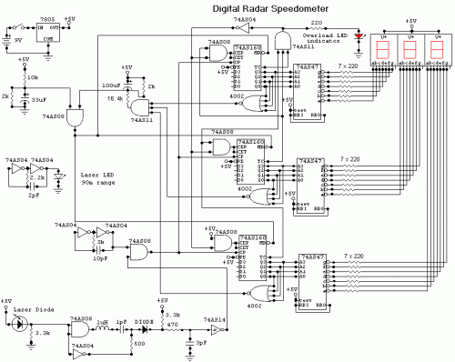
The digital radar speedometer circuit utilizes a combination of laser technology and high-speed logic components to provide accurate speed measurements. The laser LED emits a coherent light beam that travels towards the target vehicle, which reflects the light back to the radar unit. The time taken for the light to travel to the vehicle and back is measured to calculate the speed, leveraging the formula: speed = distance/time. The positioning of the radar is critical; it must be directly aligned with the vehicle to ensure that the reflected signal is received accurately by the laser diode.
The choice of the 74AS series TTL components is significant as they offer rapid processing capabilities, essential for real-time speed measurement. The circuit design must include appropriate signal conditioning to filter out noise and ensure that the signal from the laser diode is processed effectively. The output display must be designed to provide clear readability, potentially incorporating features such as backlighting for visibility in various lighting conditions.
Power management is also an important aspect of the design. The inclusion of an SPST switch allows for easy operation, ensuring that the device can be powered on and off as needed. The power supply should be stable, and consideration should be given to battery life, especially for portable applications.
Overall, the design of this digital radar speedometer combines advanced laser technology with efficient electronic circuitry to deliver precise speed measurements in a compact, user-friendly form factor.This circuit is a Digital Radar Speedometer. It allows us to evaluate the speed of any object moving, especially cars and other vehicles. The speed is calculated in kilometers per hour (KPH). Its display has three digits. This radar works with the laser reflexion. It sends laser radiation to the object and this object reflects the laser radiation to the radar. To evaluate the speed of a vehicle, we must be in front of it. In other words, the vehicle must come in our direction. The front of the radar must point the front of the vehicle. The radar has the shape of a pistol. In this radar, it has a laser LED and a laser diode. Both have a lens. The laser LED can send a spot of light to a distance of 90 m (295 ft). It`s very important that the distance range of the laser LED is 90 m, if not, the speed will not be calculated properly. The laser diode, which receives the light signal by the laser LED, must be able to detect the light which is same color as that emitted by the laser LED.
The laser diode and the laser LED must be placed one beside the other. They are protected by a tinted pane. They must be placed at the front of the radar and point the outside. The radar is powered by a 9V battery and it has a SPST switch to control its power state. The display, or the speed indicator, is placed at the rear of the radar, just on the right of the overload LED indicator. All the logic components of the circuit must be of the 74AS series and TTL type. Because they have short time of response (less than 1. 7 ns) and have high frequency supports (more than 200 MHz). The radar can evaluate the speed of an object moving between 0 to 999 km/h. After this speed, the overload LED indicator will turn on and the "999" will still displayed. The radar displays the speed during 3 seconds, after this time, it displays "zero" (0). We aim to transmit more information by carrying articles. Please send us an E-mail to wanghuali@hqew. net within 15 days if we are involved in the problems of article content, copyright or other problems.
We will delete it soon. 🔗 External reference
Related Circuits

The latest circuit diagram of the AD2496 is presented here. All modifications intended and described in the article regarding the prototype have been implemented. Additionally, two current-compensated chokes have been introduced to enhance electromagnetic compatibility (EMC) immunity. While these...
A 2-input NAND gate integrated circuit is used in the fabrication of a digital delay lamp circuit. This circuit is energized by a simple capacitive voltage rectifier, which operates by crossing the half line. The output terminal indicates the...
The circuit utilizes standard components, produces a good sine wave, and exhibits a degree of immunity to the specific operational amplifier it is designed around. However, it can be easily misunderstood, and oversimplifications regarding its operation may lead designers...
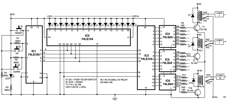
This circuit is capable of controlling one out of 16 devices using two push-to-on switches. An up/down counter functions as the master controller for the system, and visual feedback is provided through LEDs. The circuit employs IC1 (74LS193), which...
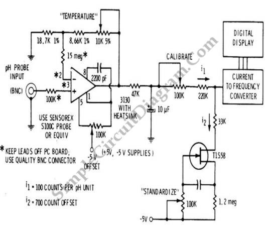
A signal conditioner for a pH meter probe requires high input impedance. The signal conditioning of the pH meter probe is achieved by incorporating a buffer. The design of a signal conditioner for a pH meter probe is critical for...
The allowable reduction in system performance. For a fire control radar, the acceptable degradation is usually expressed as a reduction in range; for example, the maximum lock-on range might be degraded by 25 percent without loss of essential defense...