
SPMC65P2408A application in one pair of mic identification directions
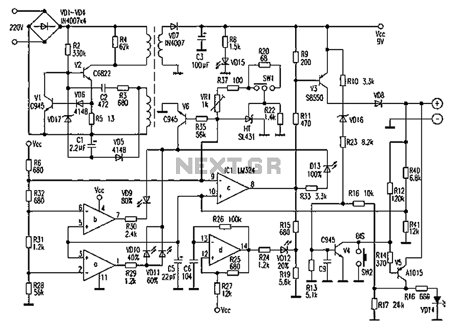
The schematic representation of the sound amplification hardware includes a structured layout that facilitates the processing of audio signals. The left section, featuring the microphone recording circuit, is crucial for capturing sound waves. The microphone converts acoustic energy into an electrical signal, which is then filtered through a capacitor to block any DC offset, ensuring that only the AC component of the sound is amplified. This filtered signal is routed to the intermediate amplification circuit, where it undergoes further amplification to achieve the desired signal strength.
The right section of the schematic is dedicated to signal processing and comparison. Once the signal is amplified, it is sent to a comparator circuit that assesses the amplitude against a predefined threshold. If the signal exceeds this threshold, it is then exported through the I/O port of the SPMC2408A microcontroller, allowing for further processing or control actions based on the sound level detected.
The SPMC2408A microcontroller is a critical component of this system, providing the necessary computational power to manage the audio signals and execute control commands. With its 28 or 32-pin configurations, it allows for flexibility in design and integration into various applications. The inclusion of features such as ADC (Analog to Digital Converter) facilitates the conversion of the amplified analog signal into a digital format, enabling more complex processing tasks. Additionally, the PWM (Pulse Width Modulation) capability offers a means to control output devices based on the processed audio signals, making this microcontroller an excellent choice for applications in audio processing, home automation, and peripheral control systems. The robust design and functionality of the SPMC2408A make it suitable for a wide range of electronic applications, enhancing the overall performance of the sound amplification hardware.The part of the hardware mainly finishes the magnification of sound, when the sound is enough large, have measured on can lead this signal into the one-chip computer ing. The hardware makes up the frame picture and is shown by 1-1. Mainly made up of CPU, analogous circuit and display circuit. The analogous circuit is used in the sound to enlarge, reveal led board can reveal the present sound direction state. In the schematic diagram, divided into three parts altogether, on the left is mic recording circuit, mic signal is after the electric capacity is block, reach the intermediate amplifying circuit, the signal after amplifying reaches the circuit of right, after comparing, export on I/O mouth of the one-chip computer. SPMC2408A is insulted 8 technical grade one-chip computer that the open company designs developing, regards SPMC65 CPU as the core, support the operation order in the location.
Have strong timing / many kinds of functions such as counter, abundant outside interrupt source and ADC, PWM, standard communication interface. Suitable for common worker`s accusing of occasion, computer peripheral control and electrical home appliances, etc.
SPMC2408A has 28 base pins and 32 base pins and two kinds of capsulation, 32 base pins have capsulated UART function more. Originally design choosing 28 base pins to capsulate, as shown in Fig. 3-1. The part of the hardware mainly finishes the magnification of sound, when the sound is enough large, have measured on can lead this signal into the one-chip computer ing.
The hardware makes up the frame picture and is shown by 1-1. Mainly made up of CPU, analogous circuit and display circuit. The analogous circuit is used in the sound to enlarge, reveal led board can reveal the present sound direction state. In the schematic diagram, divided into three parts altogether, on the left is mic recording circuit, mic signal is after the electric capacity is block, reach the intermediate amplifying circuit, the signal after amplifying reaches the circuit of right, after comparing, export on I/O mouth of the one-chip computer.
SPMC2408A is insulted 8 technical grade one-chip computer that the open company designs developing, regards SPMC65 CPU as the core, support the operation order in the location. Have strong timing / many kinds of functions such as counter, abundant outside interrupt source and ADC, PWM, standard communication interface.
Suitable for common worker`s accusing of occasion, computer peripheral control and electrical home appliances, etc. SPMC2408A has 28 base pins and 32 base pins and two kinds of capsulation, 32 base pins have capsulated UART function more.
Originally design choosing 28 base pins to capsulate, as shown in Fig. 3-1. 🔗 External reference
Related Circuits
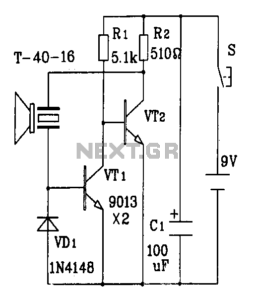
The discrete components ultrasonic transmitter circuit T/R-40-16 can emit a series of ultrasonic signals at a frequency of 40 kHz. This circuit operates at a voltage of 9V and has a current consumption of 25mA, with a control distance...
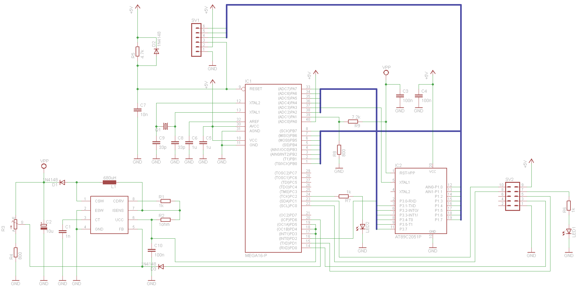
This project has been set aside for several years. It was initially intended for programming old 8051 microcontrollers, which have since become obsolete. The project was recently revisited due to the need for a programmer for the Atmel Xmega...
Atmel described a simple programmer based on the AT90S1200 (NOT the AT90S1200A) controller in their application note, AVR910 (a modification to use the AT90S2313 is also given below). The circuit is so small and simple, I was able to...
Chaolitong Phone Travel Charger for Motorola models 308, 328, 338, and 368 series mobile phone batteries. This charger features a switch for nickel-cadmium, nickel-hydrogen, and lithium-ion batteries, along with a discharge function. It operates with an AC mains input...
As power supply switching frequencies increase, higher loop crossover frequencies are necessary to keep pace with the escalating load transient slew rate demands and to reduce the number and size of filter components. For voltage-mode-controlled supplies, the voltage loop...
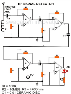
A simple electronic circuit project is presented that can be constructed by any school student for display at a school science fair. The proposed circuit is a high-gain operational amplifier (op-amp) amplifier designed to detect the slightest RF disturbances...