
Analysis schematic Chaolitong Phone Travel Charger
The Chaolitong Phone Travel Charger is designed for specific Motorola mobile phone models, ensuring compatibility with their battery technologies. The integrated switch allows users to select the appropriate battery type, optimizing charging conditions for nickel-cadmium, nickel-hydrogen, or lithium-ion batteries.
The charger operates efficiently within a voltage range of 150 to 250V AC, drawing a current of 40mA from the mains. It converts this input into a stable 300mA DC output, which is suitable for charging the designated mobile phone batteries. The circuit employs a series of diodes and resistors to monitor and indicate the charging status.
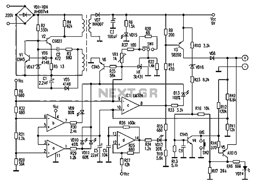
The monitoring system utilizes an integrated circuit (IC1) that provides feedback on the charging process. At no load, IC1 pin indicates a low voltage of 0.08V, which corresponds to a cutoff state for the charger. As the charging process begins, the voltage across resistors R40 and R41 is monitored. When this voltage reaches 2.63V, the output from IC1 transitions to a high state, turning on diode VD9, which signals that the battery is at 80% capacity.
As the charging continues and the voltage at IC1 reaches 2.66V, diode VD13 indicates a full charge capacity of 100%. However, the continued blinking of VD12 suggests that the battery has not yet reached its full saturation point. The final indication of a fully charged battery occurs when the voltage at IC1 reaches 6.5V, at which point VD12 turns off, confirming that the battery is fully charged.
In terms of safety features, diode VD16 is included to protect against overcurrent situations during charging, while diode VD8 prevents any reverse discharge from the battery back into the charger, safeguarding both the charger and the battery from potential damage. This comprehensive design ensures reliable performance and safety during the charging process of Motorola mobile phone batteries. Chaolitong Phone Travel Charger for Motorola to 308,328,338 and 368 series mobile phone battery. The charger has a nickel-cadmium, nickel hydrogen, lithium-ion battery switch, and having a discharge function. In 150 ~ 250V, 40mA when AC mains input, output 300 50mA DC current. The following are plotted based on physical operating principle, for your reference. on the contrary at no load, IC1 a pin is 0.08V, V6 cutoff), VD10, VD11 lights, indicating the corresponding capacity of 40%, 60%. When the partial pressure values R40, R41 rises to 2.63V, that IC1 foot equals 2.63V, after which foot via a resistor voltage divider was 2.63V, feet high output, VD9 lights corresponding to the charge capacity of 80%.
Only IC1 ? pin voltage 2.66V, feet only output high, VD13 lights corresponding to the charge capacity of 100%. Even when lit VD13, VD12 still blinks, it indicates that the battery has not yet reached full saturation. Only IC1 pin voltage 6.5V time, VD12 gradually turns off, the battery is fully charged to saturation.
VD16 played in the charge circuit, overcurrent protection role, VD8 play reverse the protective effect, avoid power charger, the battery reverse discharge.
Related Circuits
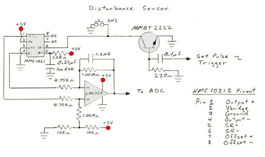
Calibrate the measurement circuit by applying a known current to the conductor and measuring the resulting voltage output. If the displacement between the sensor and conductor changes, recalibration is necessary. This sensor circuit is capable of measuring both DC...
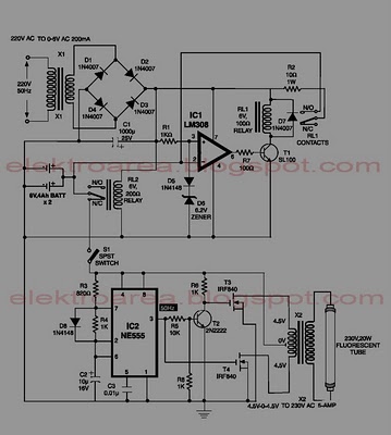
This circuit is an IC-controlled emergency light system. It automatically switches on the light during a mains failure and includes a battery charger with overcharge protection. When the mains power is absent, relay RL2 is in a de-energized state,...
A simple and interesting project schematic for a cell phone signal-activated LED circuit. The circuit will illuminate an LED when a call is made from a cell phone. This cell phone signal-activated LED circuit utilizes a basic principle of detecting...
Approximately 20 years ago, small key-holders that emitted an intermittent beep for a few seconds upon detecting a whistle were quite common. These devices utilized a specialized integrated circuit (IC) that made them unsuitable for home construction. The current...
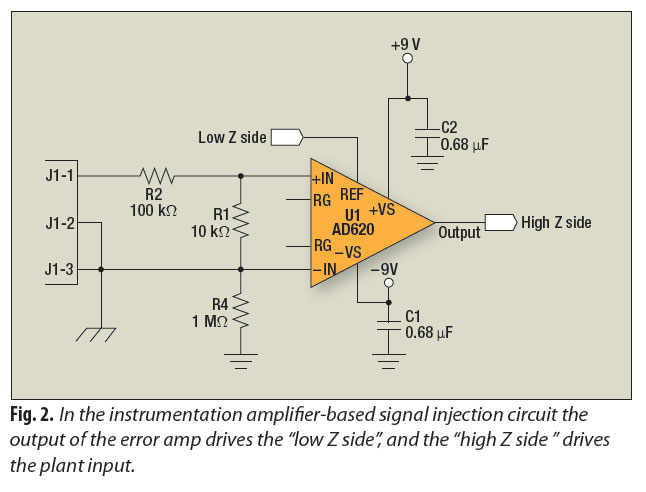
A signal-injection circuit for control-loop analysis is flat from DC to 200 kHz, isolated from chassis ground, and easily constructed with a readily available instrumentation amplifier. The signal-injection circuit is designed to facilitate control-loop analysis by providing a stable and...
The design consists of differential compound pairs of transistors with a common mode (floating) gain control connecting the emitters of the pair. The compound pairs of 2N4403 and BC549s are far more linear than any single transistor. The circuit...