
square wave generator

The multivibrator circuit serves as a fundamental building block in electronics, providing a versatile tool for generating square waves and testing various components in radio repair applications. This project typically utilizes a configuration of transistors or operational amplifiers to create oscillations.
In a basic astable multivibrator configuration, two NPN transistors are connected in a feedback loop with resistors and capacitors that determine the frequency of oscillation. The circuit operates by alternately turning on and off each transistor, producing a continuous square wave output. The frequency of the output can be adjusted by varying the resistor and capacitor values, allowing the user to tailor the signal to specific testing requirements.
For practical implementation, the circuit can be built on a breadboard for easy modification and experimentation. The output can be monitored using an oscilloscope or a frequency counter to verify the oscillation characteristics. Additionally, the multivibrator can be used to test radio components such as capacitors, transistors, and diodes by observing their response to the generated square wave.
The accompanying how-to-use guide provides step-by-step instructions for assembling the circuit, including schematic diagrams, component lists, and troubleshooting tips. This project not only enhances understanding of basic electronic principles but also equips beginners with hands-on experience in circuit design and testing methodologies.an electronic project to build a multivibator as a basic first test instrument - ideal for trouble shooting radio repairs. Includes a how to use guide. An excellent beginner project.. 🔗 External reference
Related Circuits
This is a very simple circuit utilizing a 555 timer IC to generate a square wave of frequency that can be adjusted by a potentiometer. With values given, the frequency can be adjusted from a few Hz to several...
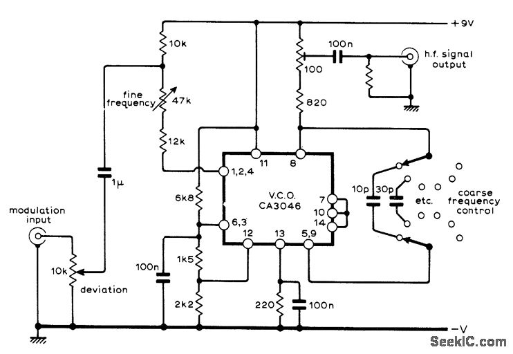
A sine-wave input can be applied to an RCA CA3046 transistor array configured as a voltage-controlled oscillator (VCO), which functions effectively as a low-distortion frequency modulation (FM) signal generator. When a sawtooth input is utilized, the same configuration operates...
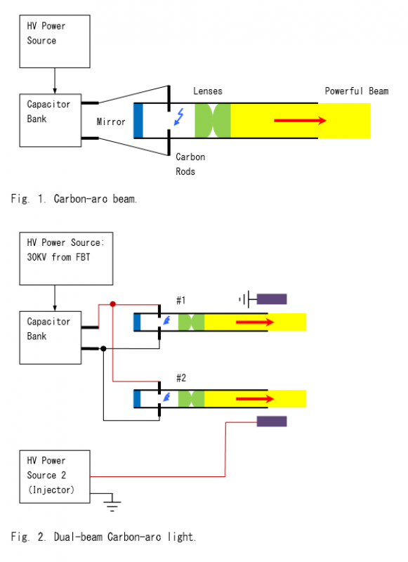
The carbon arc beam was extensively utilized as a searchlight during World War II. A basic configuration is illustrated in Figure 1. The basic beam generator can be modified as shown in Figure 2 to enable high-voltage (HV) electricity...
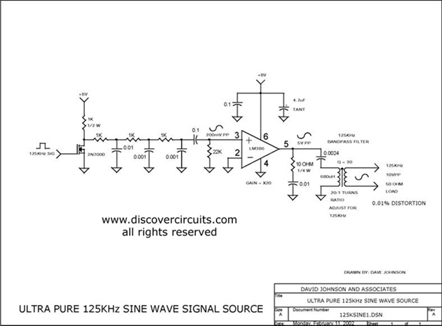
Ultra pure 125 kHz sine wave signal source. For certain RFID systems operating at 125 kHz, a very low distortion signal source is essential. The circuit presented here produces a 10-volt peak-to-peak signal. The ultra pure 125 kHz sine wave...

This is a dual Attack/Release envelope generator that has been added to the Modular Benjolin design. While not essential, it provides enjoyable functionality, particularly when used alongside the modular rungle bit output mod. The circuit is straightforward, making it...
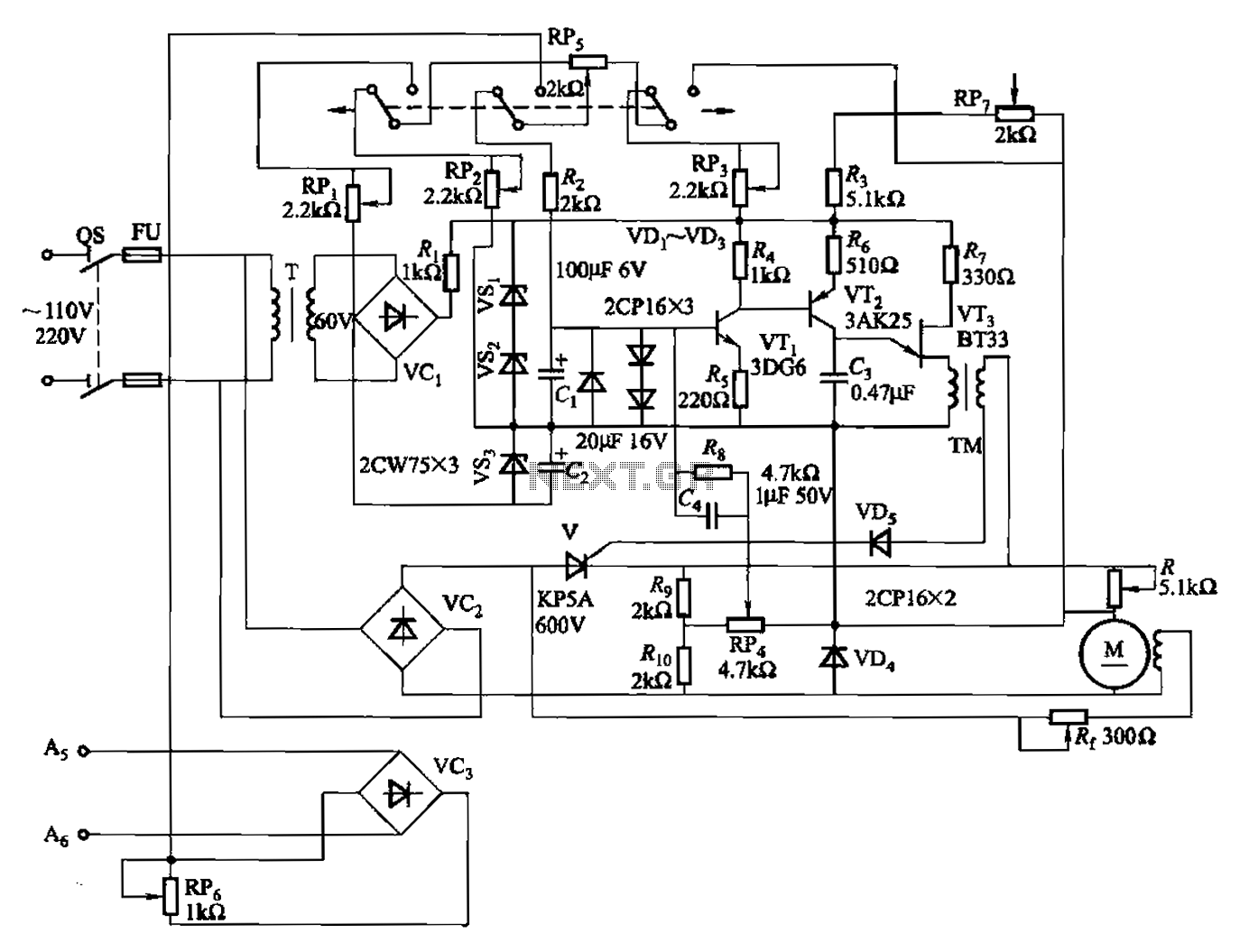
A 100W full-wave single-junction transistor trigger control circuit designed for constant or variable speed control of a wire feed motor. The input control signal consists of a voltage adjusted by the master potentiometer (RPs) and a feedback voltage from...