
Variable Square wave oscilator with 555 circuit
In order to ensure a 50% (approx.) duty ratio, R1 should be very small when compared to R2. However, R1 should be no smaller than 1kΩ. A good choice would be R1 in kilohms and R2 in megaohms. One can then select C to fix the range of frequencies.
The circuit employs the 555 timer in astable mode, where it continuously oscillates between high and low states, producing a square wave output. The frequency of oscillation is determined by the resistances R1 and R2 and the capacitance C, as per the provided formula. The 555 timer's output can be connected to various loads, such as LEDs or speakers, depending on the desired application.
To construct the circuit, connect the 555 timer's pins as follows: Pin 1 (GND) to ground, Pin 8 (VCC) to a suitable power supply (typically between 4.5V and 15V), Pin 2 (TRIG) and Pin 6 (THRESH) are connected together, and Pin 3 (OUT) will provide the output square wave. The resistors R1 and R2 are connected in series between VCC and Pin 6, with Pin 6 also connected to the capacitor C, which is then connected to ground.
The choice of R1 and R2 is critical for achieving the desired frequency range. As noted, R1 should be kept relatively small compared to R2 to maintain a duty cycle close to 50%. A potentiometer can be used for R2 to allow for easy adjustment of the frequency. The capacitor C can be varied to extend the frequency range further down into the lower frequency spectrum, depending on the application requirements.
Overall, this circuit is versatile and can be adapted for various uses, such as tone generation, timing applications, or as a clock pulse for digital circuits. Proper selection of components and configurations will ensure reliable operation across the desired frequency range.This is a very simple circuit utilising a 555 timer IC to generate square wave of frequency that can be adjusted by a potentiometer. With values given the frequency can be adjusted from a few Hz to several Khz. To get very low frequencies replace the 0.01uF capacitor with a higher value. The formula to calculate the frequency is given by: 1/f = 0.69 * C * ( R1 + 2*R2). The duty cycle is given by: % duty cycle = 100*(R1+R2)/(R1+ 2*R2). In order to ensure a 50% (approx.) duty ratio, R1 should be very small when compared to R2. But R1 should be no smaller than 1K. A good choice would be, R1 in kilohms and R2 in megaohms. You can then select C to fix the range of frequencies. 🔗 External reference
Related Circuits
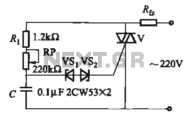
The introduction for a unidirectional thyristor trigger circuit is also applicable to the TRIAC. Several bidirectional circuits are illustrated in Figure 16-28. Figures 16-28 (a) and (b) depict a direct trigger circuit; Figure 16-28 (c) illustrates a dual diode...
This circuit consists of a light measurement circuit and a flash circuit, as illustrated in the accompanying figure. It is applicable in the POPTICS (a popular integrated camera), the Franka X-500, and the WIZEN-860S cameras. The light measurement circuit...
A resistor divider is used to attenuate a signal in a manner that is suitable for situations requiring a higher signal amplitude. A resistor divider is a fundamental circuit configuration that utilizes two resistors to create a voltage output that...
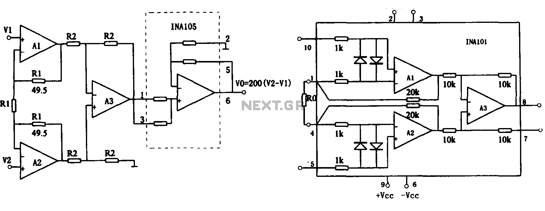
This document describes the extended common mode input voltage range of an instrument amplifier circuit. The circuit consists of three precision instrument amplifiers, A1, A2, and A3, which can be INA101 or INA102 models. The figure illustrates that A1,...

This design circuit serves as a converter utilizing the LM2623A ratio adaptive circuit to drive a digital camera motor. It generates 5 volts from input voltages that range between 1.8 and 4.5 volts. The circuit's duty cycle, while not...
At VHF, both the 1/4-wavelength monopole and the 5/8-wavelength monopole antennas are widely used. The VHF 5/8-wavelength (144 MHz) vertical monopole has long held the reputation of providing about a 3-dB gain advantage over the 1/4-wavelength vertical monopole. The...
Warning: include(partials/cookie-banner.php): Failed to open stream: Permission denied in /var/www/html/nextgr/view-circuit.php on line 713
Warning: include(): Failed opening 'partials/cookie-banner.php' for inclusion (include_path='.:/usr/share/php') in /var/www/html/nextgr/view-circuit.php on line 713