
ULTRA PURE 125KHz SINE WAVE SIGNAL SOURCE
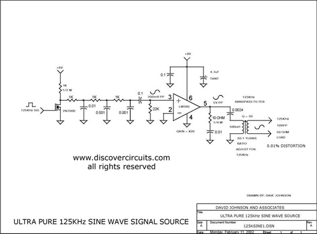
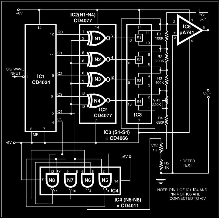
The ultra pure 125 kHz sine wave signal source is designed to meet the stringent requirements of RFID systems that operate at this frequency. The circuit utilizes precision components to ensure minimal distortion, which is critical for reliable communication in RFID applications. The output of the circuit is a 10-volt peak-to-peak sine wave, suitable for driving various RFID transponders and readers.
The circuit typically includes a waveform generator, which can be based on a precision oscillator or a microcontroller with a digital-to-analog converter (DAC). The oscillator is configured to generate a 125 kHz sine wave, and additional filtering stages may be employed to smooth the waveform and eliminate unwanted harmonics.
To achieve the desired output voltage, the circuit may incorporate an amplifier stage. This amplifier is designed to maintain linearity and low distortion while providing the necessary gain to achieve the 10-volt peak-to-peak output. Feedback mechanisms can be implemented to further enhance the stability and fidelity of the output signal.
Power supply considerations are also crucial, as the circuit must operate reliably under varying load conditions. A regulated power supply is often used to ensure that the oscillator and amplifier stages receive consistent voltage levels, thereby minimizing variations in signal output.
Overall, the design of the ultra pure 125 kHz sine wave signal source emphasizes precision, low distortion, and stability, making it an ideal choice for applications in RFID technology where signal integrity is paramount.ULTRA PURE 125KHz SINE WAVE SIGNAL SOURCE . For some RFID systems, which is at 125KHz, a very low distortion signal source is required. The circuit on this page results in a 10-volt peak-peak signal into. 🔗 External reference
Related Circuits
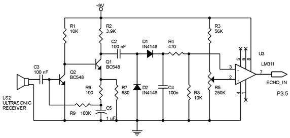
Techniques for an echo sounder used to measure ocean depth can be implemented with an ultrasonic distance measuring device. This device uses a circuit similar to the one described in the previous article, which includes a series of ultrasonic...
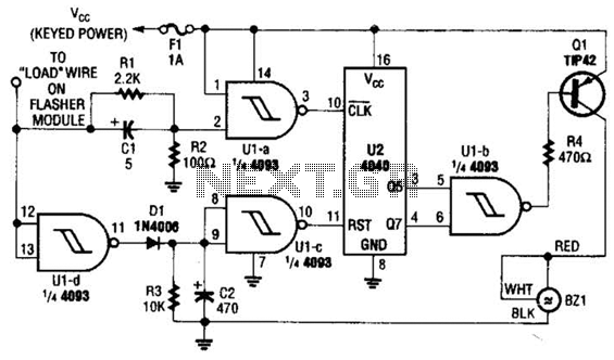
This circuit counts the flashes of turn signals. After approximately 70 flashes, a chime sounds to remind the driver to deactivate the turn signal. The period can be altered by using different taps on U2 if desired. BZ1 serves...

Circuits of this type are designed to drive LED arrays to enhance visibility and conspicuity when a vehicle is stopped or slowing down. This specific circuit emits a visual alert signal consisting of four short flashes followed by a...
This design outlines a simple 1 kHz square wave generator utilizing a few components and the LM3909 integrated circuit, which is beneficial for testing audio equipment. The circuit operates on a single 1.5V battery cell, producing a maximum output...
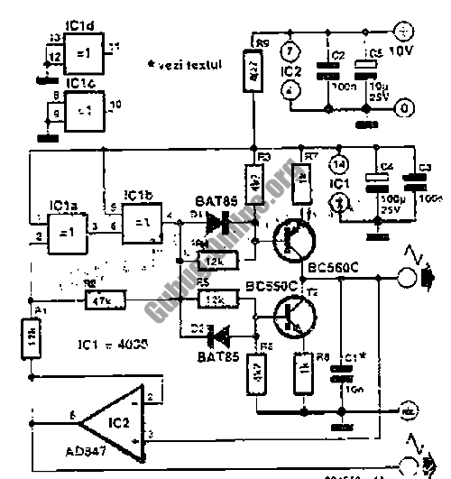
Many electronic devices rely on the shape of signals. Generating square wave signals from sine waves is relatively straightforward, while the reverse process is more challenging. The static square wave-to-sine wave converter circuit can produce an accurate sine wave...
At VHF, both the 1/4-wavelength monopole and the 5/8-wavelength monopole antennas are widely used. The VHF 5/8-wavelength (144 MHz) vertical monopole has long held the reputation of providing about a 3-dB gain advantage over the 1/4-wavelength vertical monopole. The...
Warning: include(partials/cookie-banner.php): Failed to open stream: Permission denied in /var/www/html/nextgr/view-circuit.php on line 713
Warning: include(): Failed opening 'partials/cookie-banner.php' for inclusion (include_path='.:/usr/share/php') in /var/www/html/nextgr/view-circuit.php on line 713