
SQUARE WAVE GENERATOR EMBEDDED C
The described circuit configuration employs a comparator, which is a fundamental component in signal processing applications. The comparator compares two input voltages and outputs a high or low signal based on which input is greater. In this design, the use of both positive and negative feedback is crucial for generating a square wave output.
The positive feedback loop enhances the output signal, allowing for rapid switching between high and low states. This feedback is essential for ensuring that once the comparator is triggered into one state, it remains there until the opposing input voltage becomes sufficiently dominant. The absence of a capacitor in the positive feedback path allows for immediate response to changes in input, facilitating quick transitions.
In contrast, the negative feedback path includes a capacitor, which introduces a time delay in the circuit's response. This delay is critical as it prevents the comparator from switching states too rapidly, thereby establishing a predictable oscillation frequency. The capacitor charges and discharges, effectively controlling the timing of the output changes. The interplay between the capacitor's charging time and the comparator's switching behavior results in a square wave output.
The frequency of the oscillation can be adjusted by modifying the values of the resistor and capacitor in the negative feedback loop. By selecting appropriate component values, the desired frequency can be achieved, making the circuit versatile for various applications requiring square wave signals. This circuit can be employed in timing applications, waveform generation, and as a clock signal for digital circuits, demonstrating its broad utility in electronic design.One requirement in a wide range of applications is a spontaneous source of some continuous signal, having a regular and definable wave shape. One of the most important of these is a square wave. The circuit to the right uses a comparator with both positive and negative feedback to control its output voltage.
Because the negative feedback path uses a capacitor while the positive feedback path does not, however, there is a time delay before the comparator is triggered to change state. As a result, the circuit oscillates, or keeps changing state back and forth at a predictable rate. 🔗 External reference
Related Circuits
In a sine wave oscillator circuit, a thermistor and an incandescent lamp are often utilized to stabilize the output of the circuit at a fixed value. The resistance of... The sine wave oscillator circuit is designed to generate a continuous...
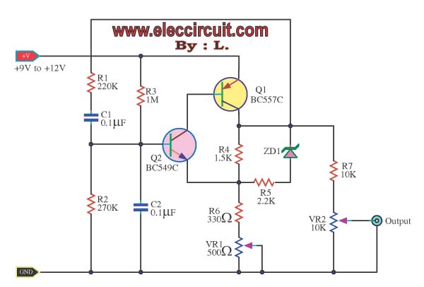
This is a kHz sine wave generator circuit built based on the configuration of an inverted Wien bridge (see C1-R3 C2-R4). R5 and R7 are used for output amplitude setting. Set R5 to read 1V RMS on an audio...
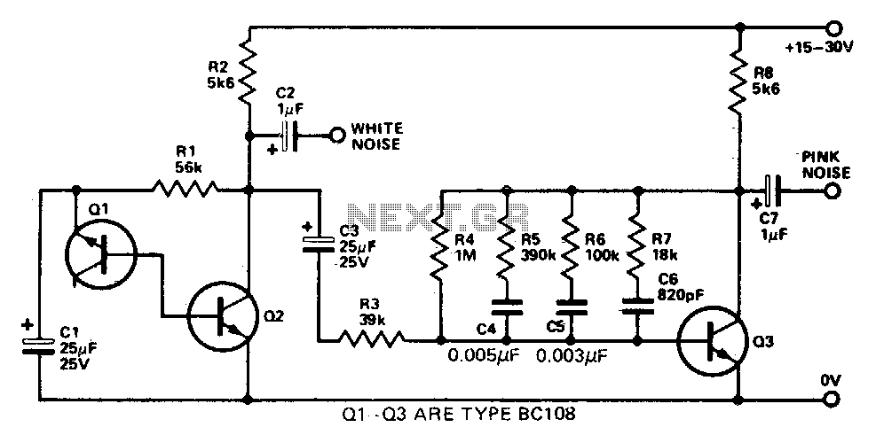
This simple circuit generates both white and pink noise. Transistor Q1 functions as a zener diode, with the base-emitter junction being reverse-biased to achieve zener breakdown at approximately 7 to 8 volts. The zener noise current from Q1 flows...
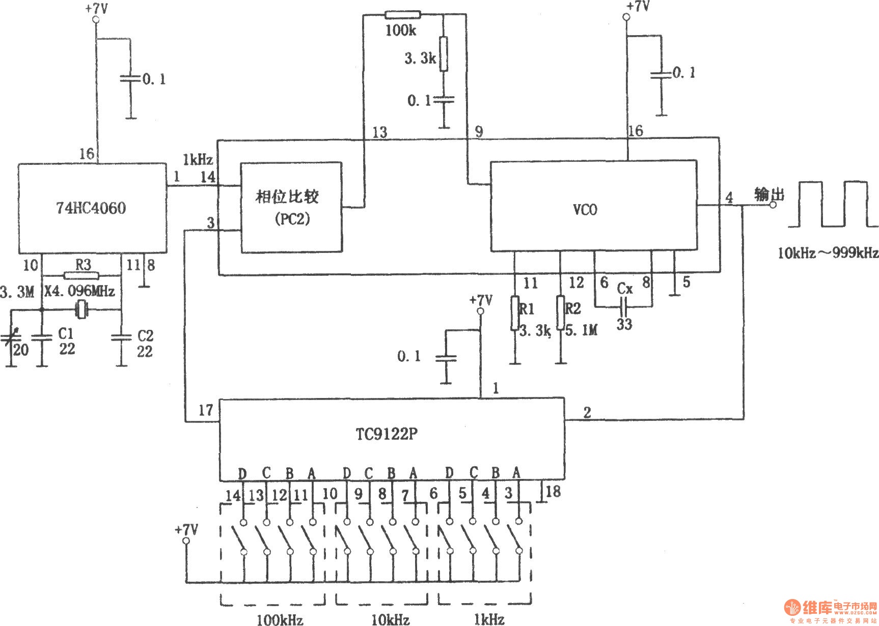
The PLL pulse generator is illustrated in the accompanying chart. The circuit represents a phase-locked loop (PLL) pulse generator. The PLL generates a fractional frequency from a crystal oscillator, producing a 1 kHz stepped frequency signal. Additionally, it outputs...
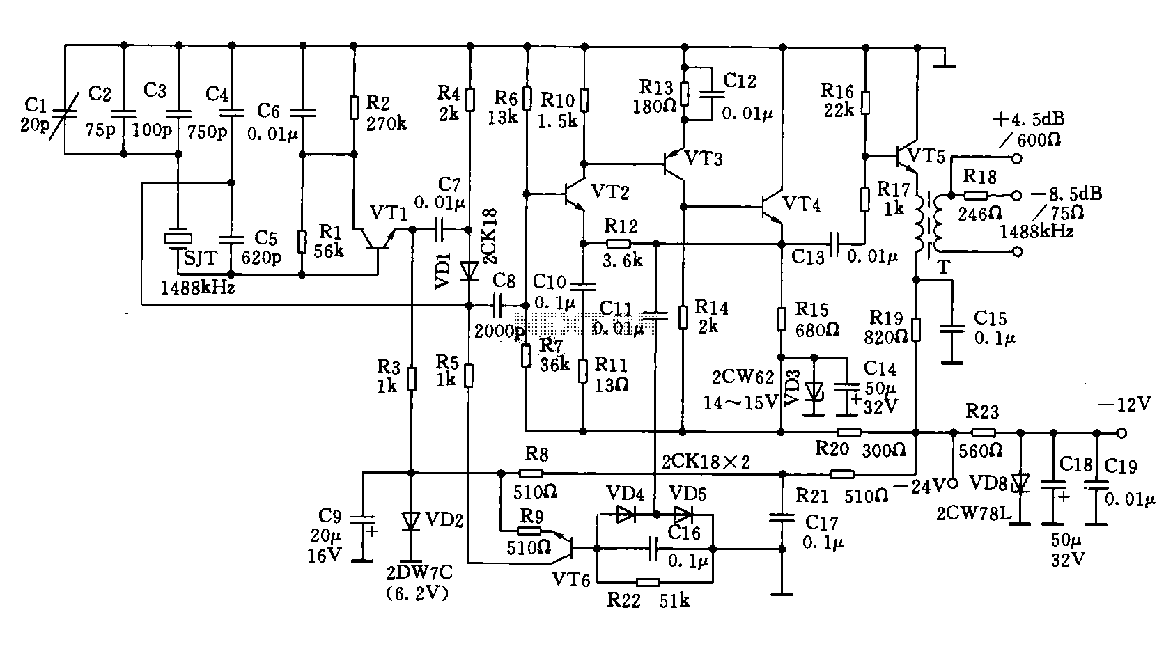
A 1488 kHz master oscillator quartz crystal resonator is utilized for frequency stabilization. The output from the frequency divider provides three different square wave signal outputs at 4 kHz, 12 kHz, and 124 kHz. The circuit includes transistors VT1,...
This is a basic 555 square wave oscillator designed to generate a 1 kHz tone for an 8-ohm speaker. In the circuit, the speaker is isolated from the oscillator by an NPN medium power transistor, which supplies more current...