
Square-Wave Oscillator
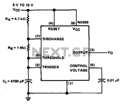
The NE555 timer in astable mode operates as an oscillator, generating a continuous square wave output without requiring any external triggering. In this configuration, the timing components RA (resistor A), RB (resistor B), and Ct (capacitor) define the frequency and duty cycle of the output waveform. The output frequency (f) is determined by the formula:
\[ f = \frac{1.44}{(RA + 2RB) \times Ct} \]
The duty cycle, which represents the proportion of time the output is high compared to the total period, can be calculated as:
\[ Duty \ Cycle = \frac{RB}{RA + 2RB} \times 100 \% \]
The inclusion of a 0.01 µF bypass capacitor on pin 5 is critical for filtering out noise that could affect the timing precision of the circuit. This capacitor stabilizes the control voltage and enhances the overall performance of the NE555 by preventing false triggering due to voltage spikes or noise in the power supply.
The upper frequency limit of approximately 100 kHz is primarily due to the internal characteristics of the NE555, including its discharge and charge times. Exceeding this limit can lead to unreliable operation, as the timer may not have sufficient time to charge and discharge the timing capacitor properly.
While there is no theoretical lower frequency limit, practical constraints arise from the values chosen for RA and Ct. As RA and Ct increase, the time constants become larger, resulting in lower frequencies. However, excessively high values can lead to longer response times and reduced performance in applications requiring rapid switching.
In summary, the NE555 timer in astable mode is a versatile component used in various applications, including clock generators, pulse width modulation, and tone generation. Its simple configuration and minimal component requirements make it a popular choice for electronic circuit designers. The NE555 is connected in the astable mode and uses only three timing components (RA, RB, and Ct. A 0.01-/aF bypass capacitor is used on pin 5 for noise immunity. The operating restrictions of the a-stable mode are few. The upper frequency limit is about 100 kHz for reliable operation, as a result of internal storage times. Theoretically, it has no lower frequency limit, only that which is imposed by Rt and Ct limitations. 🔗 External reference
Related Circuits
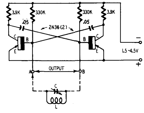
Transistors are increasingly being utilized in various applications. Many circuits employing transistors have been developed based on previous designs that used vacuum tubes. The following chapters present unique applications that leverage the advantageous properties of transistors. The described circuits...
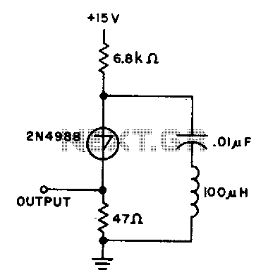
The capacitor charges until the switching voltage is reached. When the switch (SUS) is activated, the inductor causes the current to oscillate. When the current through the switch drops below the holding current, the device turns off, and the...
This CMOS square-wave oscillator utilizes the 4047 multivibrator circuit, suitable for both monostable (one-shot) and astable applications. In the provided configuration, the 4047 operates as an astable multivibrator. The circuit features three outputs from the 4047, with the first...
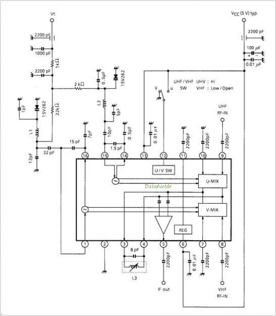
TA1317ANG is a deflection processor integrated circuit (IC) designed for large and wide picture tubes. It includes an electronic width (EW) correction circuit, a vertical distortion correction circuit, and a dynamic focus correction circuit. The device can control various...
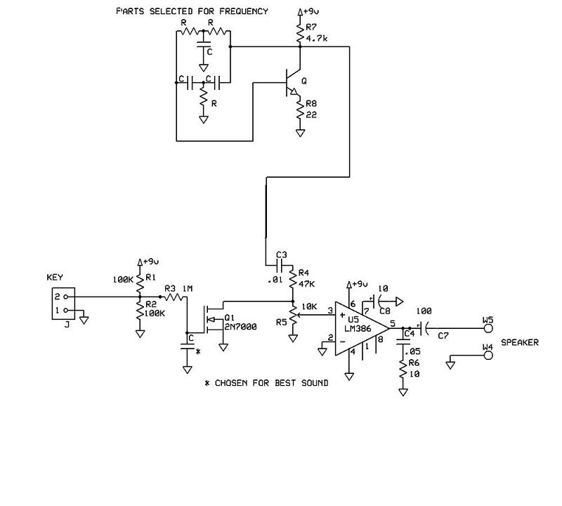
A schematic for a code practice oscillator is needed, which can be connected to a keyer. The desired setup involves using a Picokeyer, allowing the oscillator to be plugged into the key jack of the Picokeyer. The output should...
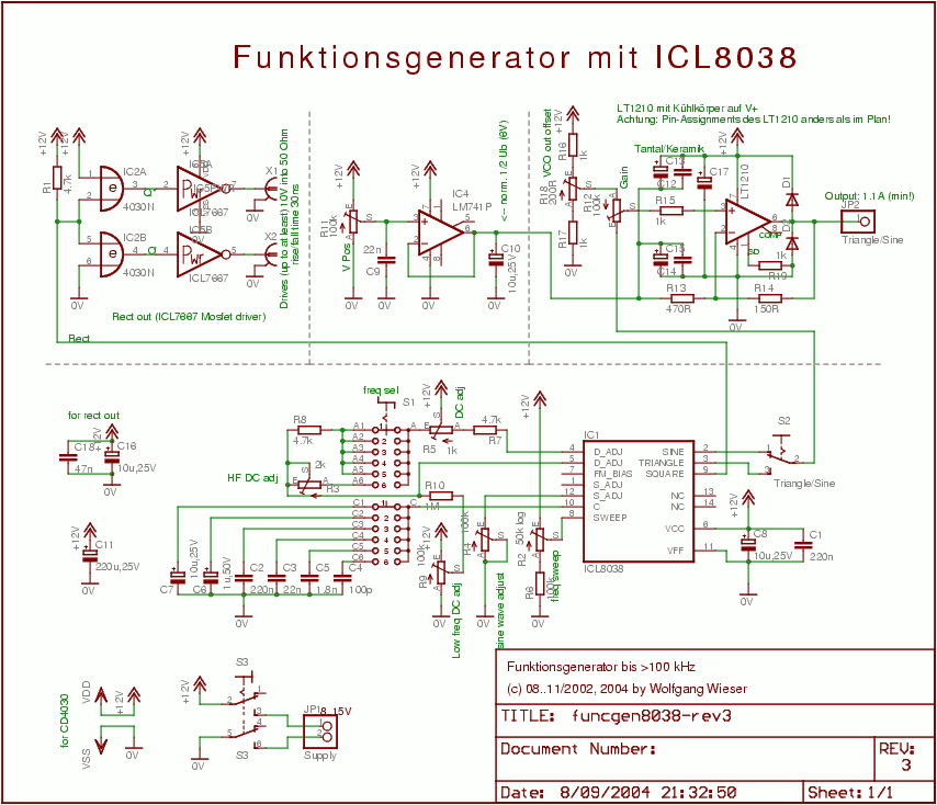
The circuit design is relatively straightforward. It features a Voltage Controlled Oscillator (VCO) utilizing the ICL8038 along with supplementary components, a sine and triangle output stage using the LT1210, and a CMOS-compatible output stage driven by the MOSFET driver...