
Sine wave code practice oscillator
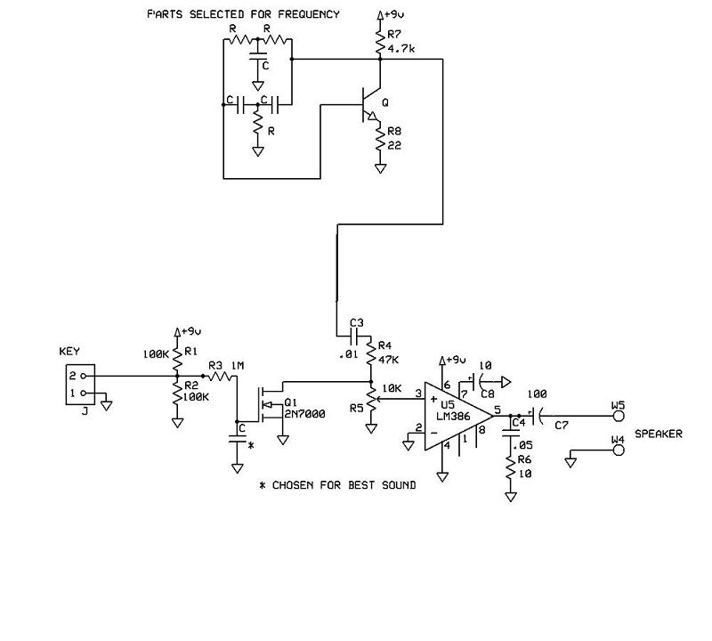
The requested schematic for a code practice oscillator is designed to facilitate Morse code practice by generating audio tones that can be adjusted for frequency. This oscillator should be compatible with a Picokeyer keyer, enabling seamless integration.
The circuit typically employs a simple sine wave oscillator configuration, which may include components such as operational amplifiers or a function generator IC to produce the desired sine wave output. The oscillator's frequency can be modulated using a variable resistor or potentiometer, allowing the user to adjust the tone to their preference.
For the output stage, the circuit should include a power amplifier to drive an 8-ohm speaker effectively. This can be achieved using a transistor or an integrated audio amplifier IC, which will take the oscillator's output and amplify it to a suitable level for audible sound production.
Powering the circuit with a 9V battery is a practical choice, providing sufficient voltage while maintaining portability. Proper decoupling capacitors should be included to ensure stable operation and reduce noise in the circuit.
Overall, the schematic will consist of an oscillator section, an adjustable tone control, and an output stage capable of driving an 8-ohm speaker, all powered by a 9V battery, creating an effective tool for Morse code practice.I`m looking for a schematic for a code practice oscillator that can be hooked up to a keyer. I have a Picokeyer so I`d like to be able to just plug the oscillator into the key jack of the Picokeyer. Output would be to an 8 ohm speaker. Tone should be adjustable. Power could be a 9v battery. I`ve found lots of references to square wave code oscillator circuits. I found only one for a sine wave oscillator. Unfortunately, I can`t remember where I saw it and haven`t been able to find it again. .. 🔗 External reference
Related Circuits
After several years, the NMS8280 was utilized again for HAM radio purposes. When transmitting a signal, radio amateurs must always identify themselves by providing their callsign, which also applies to video signal transmission. A program was created using the...
The oscillator employs a fundamental quartz crystal, capable of achieving an oscillation frequency of up to 10 MHz. The oscillator circuit is calibrated to the resonant frequency of the crystal. A capacitor, designated as C, with a value of...
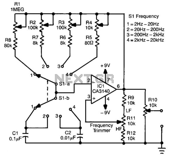
This circuit generates a square wave with a frequency range of 2 Hz to 20 kHz. It employs an operational amplifier in a relaxation oscillator configuration. The output voltage is approximately 15 V peak-to-peak. Resistors R1 through R4 serve...
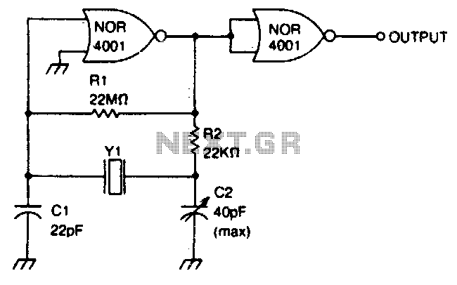
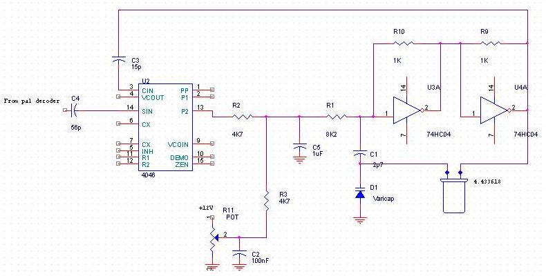
This circuit operates within a frequency range of 0 MHz to 2 MHz. The frequency can be finely adjusted to a specific value using the trimmer capacitor C2. Additionally, the second NOR gate functions as an output buffer. The circuit...
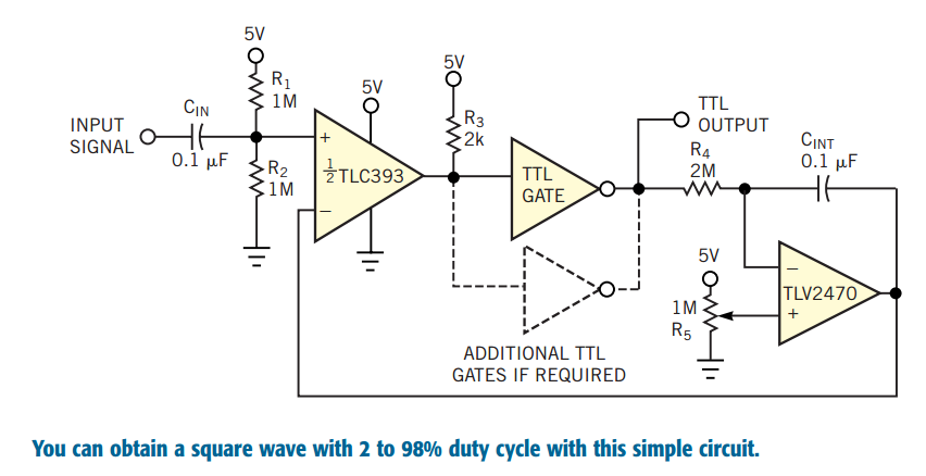
Converting periodic waveforms to square waves is an integral part of extracting a clock signal from data, creating waveform generators, and making timing-pulse generators. Any square-wave-conversion circuit is more valuable when the square wave's duty cycle is variable and...
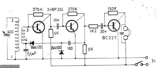
Oscillating circuits (coils) are constructed on a ferrite bar. For long wave reception, winding "1-2" consists of 135 turns, while winding "3-4" has 20 turns. For medium wave reception, winding "1-2" has 75 turns, and winding "3-4" has 7...