
SR 6m/2m Converter
This kit is designed to facilitate the reception of VHF signals by converting them to HF frequencies that can be processed by the Softrock Lite + Xtall RX V9.0. The integrated circuit design allows for efficient signal conversion through a combination of pre-amplification, mixing, and filtering. The double-balanced mixer (U1) plays a critical role in generating the intermediate frequency (IF) from the combination of the incoming VHF signal and the Local Oscillator (LO) signal. The choice of components, including the pre-amplifier (Q1) and transformer (T1), ensures that the signals are adequately conditioned for further processing by the RX's Quadrature Sampling Detector.
The Local Oscillator frequency is crucial for ensuring that the resultant IF frequency aligns with the quadrature clock frequency of the V9.0 RX, allowing for precise tuning and signal processing. The necessity to swap the I and Q leads for certain bands underscores the importance of understanding the circuit's operation and the relationship between the LO frequency and the incoming VHF signal.
The kit's design promotes an educational approach to construction, enabling builders to gain hands-on experience with RF circuit assembly while ensuring that each stage of the build is manageable. This systematic approach, coupled with available resources for troubleshooting and advanced techniques, provides an accessible entry point into the world of RF electronics and signal processing.This kit, designed by Jan G0BBL and implemented and distributed by Tony KB9YIG, is a plug-in board for the Softrock Lite + Xtall RX V9. 0 which down-converts VHF signals in the 2m and 6m bands to HF signals that can be received on the V9.
0 RX. Also documented here is a 4m version (four metres, for our EU friends), courtesy of Bob G8VOI. The parts f or the 4m version are included in the kit, with the exception of two capacitors (2. 2 pF and 120 pF ceramic) which the builder must obtain. In addition, the schematic calls for band-specific parts C15 and L5; however, these were subsequencly dropped from the final design as unnecessary. The builder will find invaluable information at the website of Fred PE0FKO, especially the setup of the software and firmware, as documented in the excellent users manual from Bob G8VOI.
The converter plugs into the Softrock Lite + Xtall V9. 0 RX at the on-board jacks J1 and J2. Power comes from the V9. 0 RX`s 12 Vdc bus (on pin 3 of J2). The down-converted VHF signals are fed to the V9. 0 RX QSD circuit via pins 7-9 of J1/P100. The incoming signal from the Antenna terminal (or, via a jumper wire from J1/P100 Pin 1), e. g. , 144MHz, is pre-amplified by Q1 and fed to a double-balanced mixer, U1. U1 also receives a Local Oscillator signal via pin 4 of V9. 0 RX`s J1. This local oscillator signal must be at a frequency (e. g. , 115. 2 MHz) which, when mixed with the incoming 144 MHz signal, will produce both a difference (144 - 115. 2 = 28. 8MHz) and the sum (144 + 115. 2MHz = 259. 2MHz). Fred PE0FKO`s Firmware handles this translation. See notes below on how to program the Local Oscillator to result in an IF frequency that is equal to the V9.
0 RX`s quadrature clock frequency. The output of the mixer at U1`s pin 2 is filtered to remove the sum (image frequency). The (difference) IF is transformed into two anti-phase signals by T1 and fed to the V9. 0 RX`s Quadrature Sampling Detector via pins 7-9 of J1 (in lieu of the usual BPF output for normal HF RX). Tuning the band is then done in the V9. 0 RX on signals centering around the quadrature clock frequency (converted in software to the corresponding VHF frequency display values.
Care must be taken to calculate the LO frequencies so as to arrive at an IF that is exactly equal to the quadrature clock frequency. This is done using a multiplier factor that is specific to the band. This multiplier for 2m is 0. 8; for 4m and 6m it is (4/3). For the bands below 2m (i. e. , 6m and, in the EU, 4m) the LO frequency will be higher than the desired VHF frequency. This calls for swapping the I and Q leads from their normal ring/tip orientation. For the non-expert builders among us, this site takes you through a stage-by-stage build of the kit. Each stage is self-contained and outlines the steps to build and test the stage. This ensures that you will have a much better chance of success once you reach the last step, since you will have successfully built and tested each preceding stage before moving on to the next stage.
If you are not experienced at soldering (and even if you are somewhat experienced at soldering), refer to Tom N0SS`s excellent tutorial on basic soldering techniques. For the more adventurous, there is a process using solder paste and an electric oven called the reflow process, which can be used to install all the SMT chips to one side of the PC Board.
This is documented by Guenael Jouchet in the following Youtube segment: You will need a well-lit work area and a minimum of 3X magnification (the author uses a cheap magnifying fluorescent light with a 3X lens. This is supplemented by a hand-held 10 X loupe - with light - for close-in inspection of solder joints and SMT installation.
You should use a cookie sheet or baking pan (with four sides raised approximately a half an inch) for your actual work space. It is highly recommended for building on top of in order to catch stray parts, espec 🔗 External reference
Related Circuits
Switching regulator subsystems are designed for use as DC to DC converters. The 3V to 40V DC converter circuit utilizes switching regulators, which are increasingly favored over linear regulators due to the demand for higher conversion efficiency in modern...
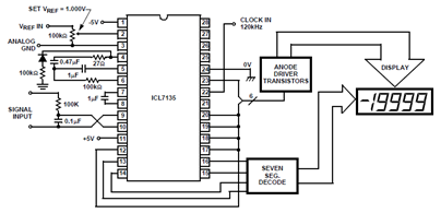
The schematic below shows the ICL7135 integrating analog-to-digital converter (ADC) functional diagram. According to the datasheet, an integrating converter is the right choice for panel meters and digital voltmeter applications. It can also be used for reducing line frequency...
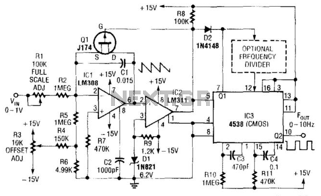
In this circuit, capacitor CI is charged to a fixed reference level and then discharged. The integrator IC1 charges CI until IC1 has a -6.2 V output, at which point comparator IC2 outputs a low signal. FET Q1 triggers...
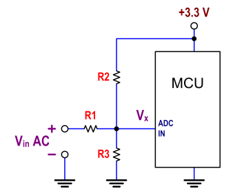
The ATtiny24 microcontroller's ADC is utilized to record an AC signal, which operates within a voltage range of 0 to 3.3V. A precision rectifier is employed to eliminate the negative portion of the signal. The circuit incorporates an LMC6484...
This document presents a straightforward and practical schematic for a 12V to 3V converter circuit. The output current of the circuit is approximately 1A. The 12V to 3V converter circuit is typically designed using a linear voltage regulator or a...
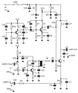
This is the circuit diagram of an audio/video modulator. The circuit converts audio and video signals into a UHF TV signal, allowing a video signal from a camera or other source to be connected to a standard TV set....