
SR63 holiday lights ASIC
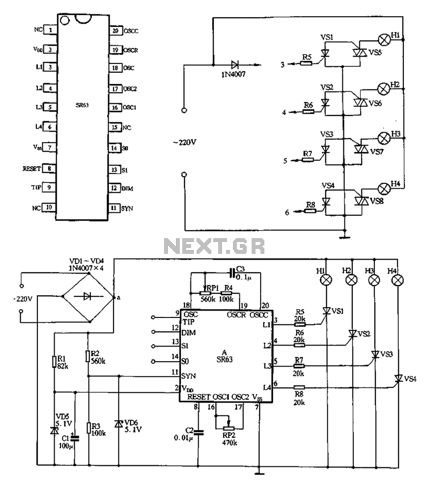
The circuit described operates by first converting an AC voltage of 220V to a DC voltage using a bridge rectifier formed by diodes VD1 to VD4. The output is then utilized to power four lights (H1 to H4) directly, ensuring reliable illumination. Additionally, a secondary pathway involves a buck converter (R1) and a voltage regulator (VD5) to step down the voltage to approximately 5V DC, which is essential for powering low-voltage components within the circuit.
The voltage divider composed of resistors R2 and R3 serves a dual purpose: it not only stabilizes the voltage supply to manifold A but also generates a synchronization signal that is critical for the timing functions of the circuit. The oscillator circuit, which includes RP1, R4, C3, and SR63, is designed to produce a variable frequency output. By adjusting RP1, the frequency of oscillation can be modified, which in turn influences the chase speed of the lights, allowing for dynamic visual effects.
Furthermore, RP2 is integrated into the dimming oscillator circuit, providing the capability to adjust the brightness of the lights. The adjustment of RP2 affects both the speed and the contrast of the light output, enabling a range of visual presentations from bright to dim settings.
The control terminals for the four lights can be connected to a switch or configured for a specific operation mode, as indicated in the referenced table 2-41. This flexibility allows for the customization of the lighting effects based on user requirements or specific application scenarios, making this circuit suitable for various lighting control applications.220V AC after VDI ~ VD4 bridge rectifier, the output of a point, all the way to direct electricity for lights H1 ~ H4; another way through Rl buck, VD5 regulator, about 5v DC o utput voltage, the electricity supply manifold A. R2, R3 form a voltage divider provides a synchronization signal for the manifold A. RP1, R4, C3 and SR63 within the oscillator circuit system, adjust the value of the RPI system can change the oscillation frequency rate, muscle and can be adjusted four lights chase speed. RP2 inner circuit dimming oscillator circuit, the adjustment value of RP2 can change the speed and dimming lights bright and dark contrast.
FIG DIM, Sl, so, TIP missed four control terminal t in the actual production should be connected with a switch or a switching operation according to the pattern need to refer to table 2-41.
Related Circuits
This example demonstrates a robust design featuring novelty lights that flash in a specific sequence, utilizing a 1-3-2-4 vault chase mode. The circuit includes diodes VD1 to VD4, which form a bridge rectifier, converting AC voltage to a full-wave...
The 555 timer IC is connected for Astable Operation, the clock pulses are fed to the 4017 IC via the 10K resistor. The 4017 is a 10 stage counter, therefore the sequence of the traffic lights is spread over...
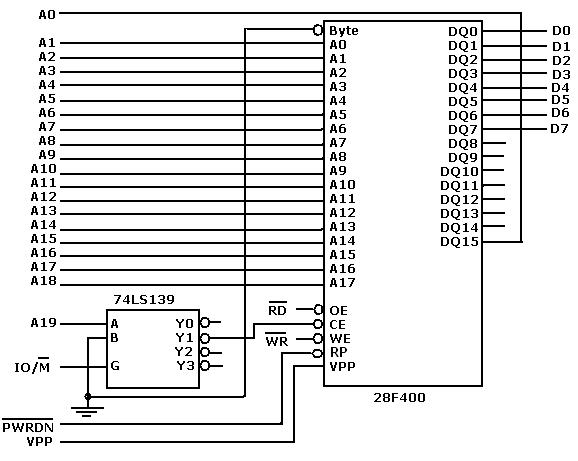
Flash memory, also known as flash RAM, is a type of non-volatile semiconductor memory device that retains stored data even when not powered. It is an enhanced version of electrically erasable programmable read-only memory (EEPROM). The primary distinction between...
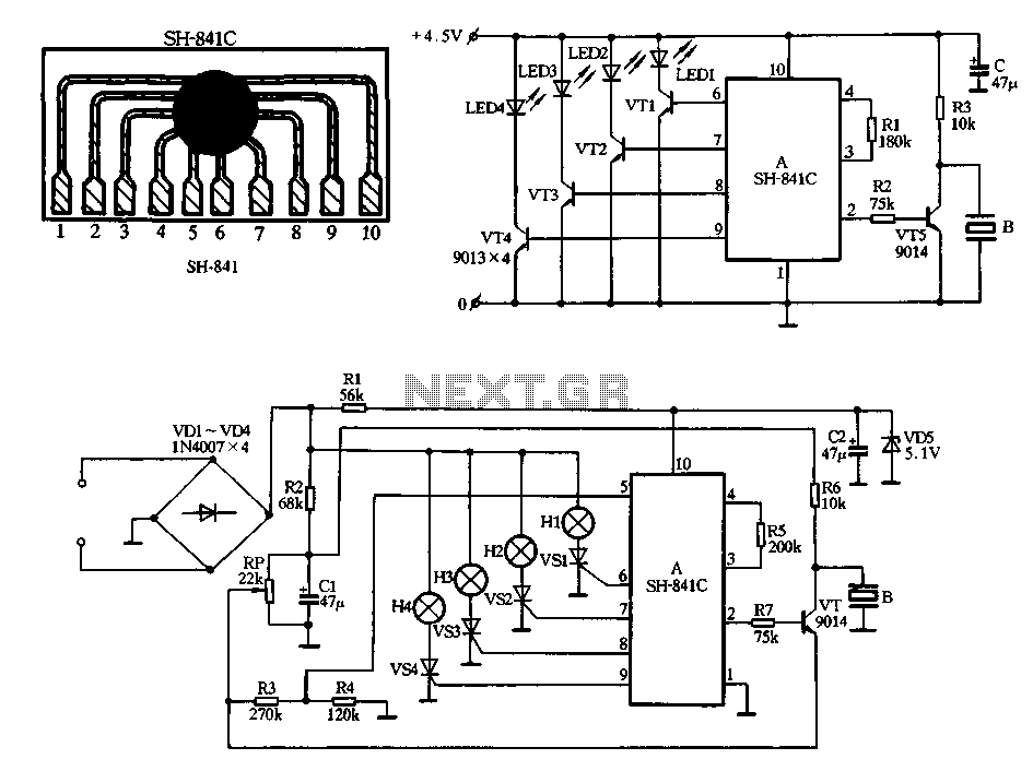
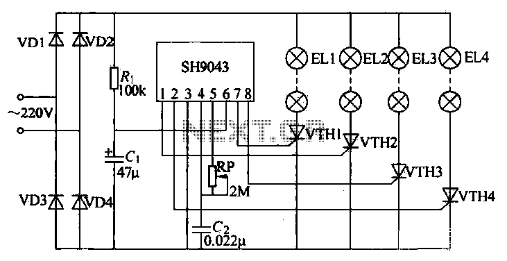
Figure 2-78 illustrates the SH-841 as the central component in a holiday lights controller. It utilizes SCRs VS1 to VS4 to drive light strings H1 to H4, causing them to flash. The operating voltage is sourced from AC through...
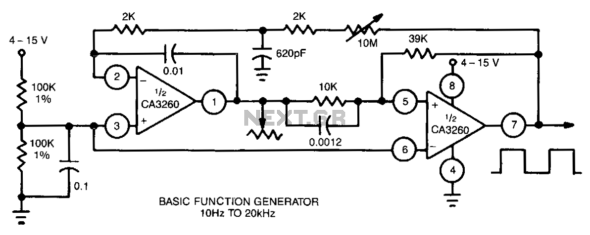
This function generator utilizes a CA3260 BiMOS operational amplifier to perform both integrator and switching functions. A 620-pF capacitor and a 2-kΩ resistor are employed to shape the feedback square wave, minimizing spikes. The device covers the full audio...
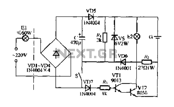
Figure 283 illustrates a blackout emergency lighting controller designed for straightforward external installation with two leads. This controller can directly replace the P Chan Tong Ge opening. Under normal power conditions, it functions like a conventional switch to control...