
SSR Power Control Unit
The SSR Power Control Unit Circuit is designed to provide efficient control of electrical loads using solid-state relays, which offer advantages such as faster switching times, longer life spans, and reduced electromagnetic interference compared to traditional electromechanical relays.
In this circuit, the SSR control box is the central component responsible for generating and supplying the necessary control voltage to activate the relay. The SSR operates by using semiconductor devices to switch the load on and off, allowing for precise control over the power delivered to the load.
Typically, the control voltage input to the SSR can be derived from a microcontroller or other control circuitry, which sends a low-voltage signal to the SSR. This signal is then used to trigger the relay, which in turn controls a higher voltage and current load. The SSR is characterized by its high input-to-output isolation, which ensures that the control circuit remains unaffected by the high voltage side of the system.
The circuit may include additional components such as resistors for current limiting, capacitors for noise filtering, and possibly opto-isolators to further enhance isolation and protect the control circuitry from voltage spikes. The layout of the circuit should be designed to minimize inductive and capacitive coupling, ensuring reliable operation in various electrical environments.
Overall, the SSR Power Control Unit Circuit is an essential design for applications requiring efficient and reliable control of high-power loads, providing an effective solution for automation and control systems in industrial and commercial settings.This circuit shows about SSR Power Control Unit Circuit Diagram. Features: SSR control box provides the control voltage for the relay. Component: . 🔗 External reference
Related Circuits

This is a circuit for Closed-Loop Automatic Power Control for RF Applications. The circuit utilizes a log detector (AD8318) and a variable gain amplifier (VGA) (ADL5330). The Closed-Loop Automatic Power Control (APC) circuit is designed to maintain a consistent output...
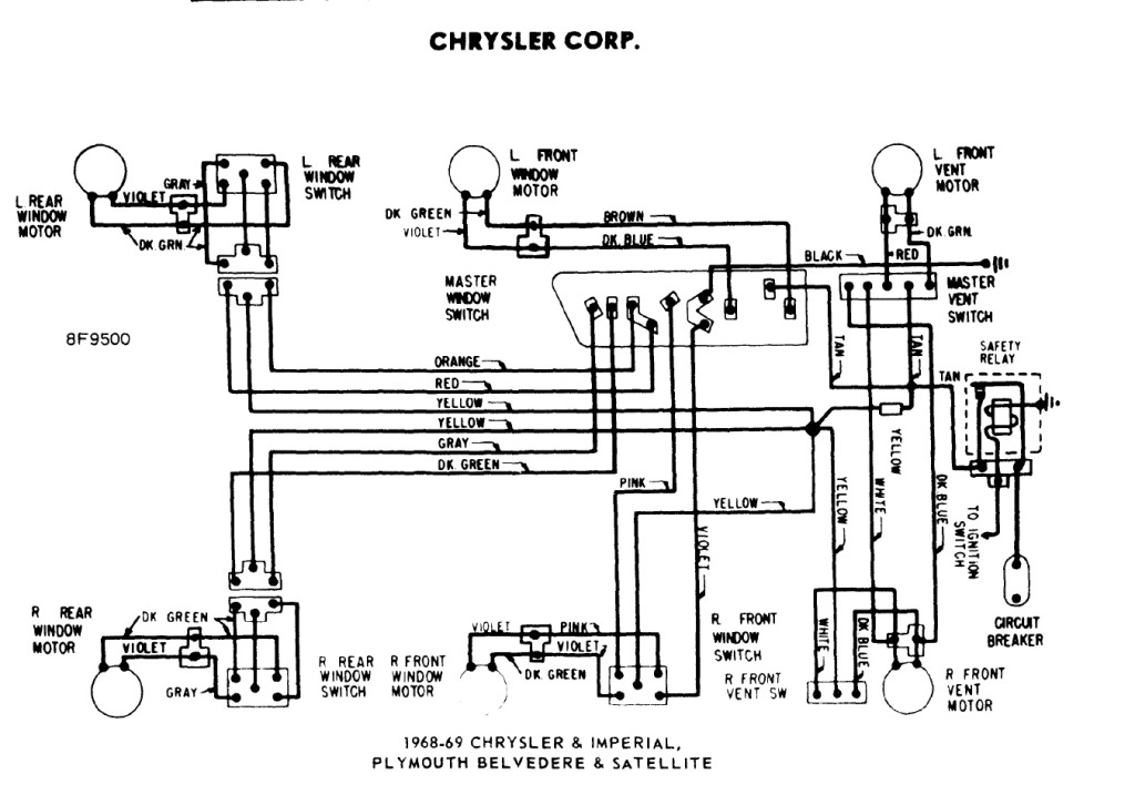
The power windows operate slowly, but connecting 12 volts directly to the motors allows them to function properly. A previous discussion mentioned using a common 5-pin ice cube relay, but there was no confirmation of its effectiveness. The power...
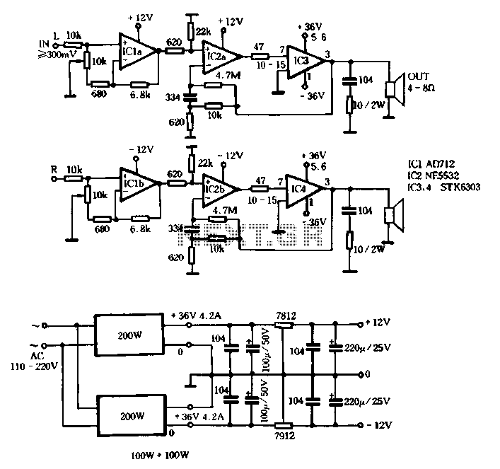
The T amplifier circuit schematic section is illustrated in Figure 3-51. It utilizes the Japan Sanyo STK6303 Pina, which is a high-power thick film integrated circuit. The maximum power supply voltage is 36V, and the output current can reach...
The foundation of this amplifier is detailed in Project 03, which does not claim to be cutting-edge; the base design is over 20 years old. It is straightforward to assemble, utilizes readily available components, and is stable and dependable....
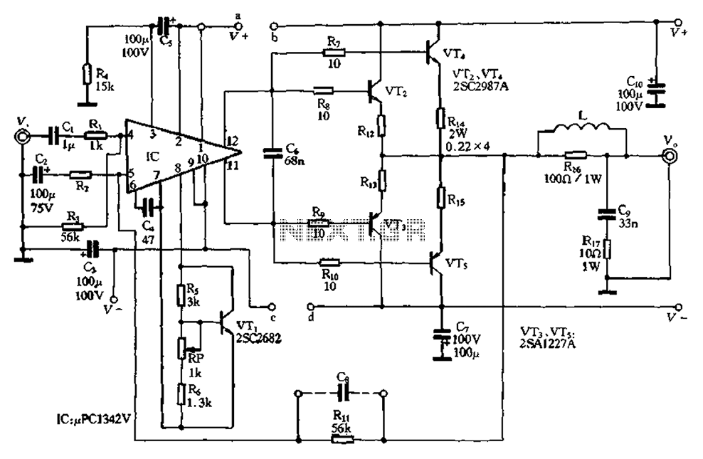
The pLPC1342V and NE are two companies involved in a tube amplifier circuit utilizing 2SA1227A and 2SC2987A transistors, achieving a maximum output power of up to 120W with a cutoff frequency of up to 500 MHz. The circuit, illustrated...

This car audio amplifier circuit is based on the LA47536 audio amplifier integrated circuit designed by Sanyo. This audio amplifier circuit is specifically designed for car audio power amplifiers. The LA47536 car audio amplifier IC features four output channels...