
Updated 60-100W Hi-Fi Power Amplifier
ally a new design. This new amp (like the original) is based on an amp I originally designed many years ago, of which hundreds were built. Most were operated as small PA or instrument amps, but many also found their way into home hi-fi systems.
The amp is capable of driving 4 Ohms, but it is starting to push the limits of the transistors, however, even when used at 4 Ohms, very few failures were encountered. This amplifier, although very simple, is capable of superb performance. This is not an amp to be under estimated, as the sonics are very good indeed, and this is due (in part, at least) to the inherent simplicity of the design.
The amp is exceptionally quiet, and is reasonably tolerant of difficult loads. It is an ideal amplifier for biamped systems, and may be operated in bridge mode (BTL) if the selected output transistors have the necessary power ratings (e. g. MJ21193/4) I have heard nothing but praise from those who have built this amplifier the only feedback I have received has been very positive indeed.
The sound quality is up there with the very best. Highly recommended ! Note that like the original, there is (still) no output short circuit protection, so if speaker leads are shorted while the amp is working with a signal, there is a very real risk of the transistors being destroyed. The specifications are very similar to those of the original project, but the use of a current sink in the differential pair input stage means that there is virtually no thump at turn on or off.
I have also added the ability to adjust the quiescent current, and with the transistors specified the amp will provide 100W into 8 ohms, at a maximum supply voltage of +/-42V. This supply is easily obtained from a 30-0-30V transformer. As can be seen, it is not a complex amp, but the performance is excellent. Connections are provided for a SIM (Sound Impairment Monitor), and there is also a resistor (R17) added to allow bridging.
This resistor connects to the output of the other amplifier (the master). When used in this way, the input should be grounded do not omit the capacitor, or DC offset will be too high. When used in bridge mode (also called BTL Bridge Tied Load), the SIM should be taken from the master amplifier only.
For use into 4 ohms (including bridging into 8 ohm loads), do not exceed +/-35V (from a 25-0-25V transformer). Most applications will be satisfied with the lower voltage, and the reliability of the amp is assured with almost any load.
In bridge mode, this amp will happily produce 200W into 8 ohms, and will do so reliably even for continuous high power levels. Never attempt to operate the amp in bridge mode into 4 ohms, as this represents an equivalent load to each amp of 2 ohms.
The amp was not designed to handle this, and will fail. D1 is a green LED, and should be a standard type. Don`t use a high brightness LED, or change the colour. This is not for appearance (although the green LED looks pretty neat on the board), but for the voltage drop different coloured LEDs have a slightly different voltage drop. VR1 is used to set the quiescent current, and normally this will be about 100mA. The amp will work happily at lower current, but the distortion starts to be noticeable (on a distortion meter) at less than around 40mA.
The Class-A driver (Q4) has a constant current load by virtue of the bootstrap circuit R9, R10 and C5. Stability is determined by C4, and the value of this cap should not be reduced. With fast output transistors such as those specified (2SC3281 and 2SA1302), power bandwidth will be good to over 30kHz.
With the suggested and recommended 35V supplies, Q4 and the output drivers (Q5 and Q6) will normally not require a heatsink. With 4 ohm loads, you may find that a heatsink for Q5 and Q6 is needed, but my experience is that these transistors should not get hot under most operating conditions.
Before applying power, make sure that VR1 is set to maximum resistance to get minimum quiescent current. This is very important, as if set to minimum resistance, the quiescent current will be very high indeed (probably enough to blow the output transistors!).
Since I have boards available for this amp, I will obviously suggest that these be used, as it makes construction much easier. All resistors should be 1/4W 1% metal film for lowest noise, with the exception of R9, R10 and R15 which should be 1W types, and R13, R14 must be 5W wirewound.
The bootstrap capacitor (C5) needs to be rated at at least 35V, but the other electrolytics can be any voltage you have available. The trimpot (VR1) should ideally be a multiturn, but an ordinary single turn pot can be used. Setting the current will be a little more difficult with a single turn pot, and they are not as reliable.
A pair of these amps will be quite happy with a 1oC/W heatsink for normal hi-fi use. Consider using a fan if you are going to push the amp hard. Remember there is no such thing as a heatsink that is too big. The following is not comprehensive, since the design is quite new, and I have not had a chance to measure everything as yet. To give you an idea, this is what I have found so far The frequency response is dependent on the value for the input and feedback capacitors, and the above is typical of that when the specified values are used.
The high frequency response is fixed by C4, and this should not be changed. Operation into 4 ohm loads is not recommended with the 42V supplies. Peak dissipation will exceed 110W in each output transistor, leaving no safety margin with typical inductive loads. All supply voltages are at full power your transformer may not be capable of maintaining regulation, so power may be slightly less than shown.
This figure is typical, and is dependent on the regulation of the power supply (as in 2, above). Worst case power with 8 ohm loads is about 50W, but the supply needs to be fairly ratty for the power to drop this low. Four of these amps in a biamped arrangement will give you prodigious SPL, and is similar to the arrangement I am using.
Coupled with a Linkwitz-Riley crossover, the amplifiers can be mounted in the back of the speaker box, so only signal and power are needed for a complete system that will leave most commercial offerings for dead. If you do not have a dual output bench power supply Before power is first applied, temporarily install 22 Ohm 5 W wirewound safety resistors in place of the fuses.
Do not connect the load at this time! When power is applied, check that the DC voltage at the output is less than 1V, and measure each supply rail. They may be slightly different, ifier. 🔗 External reference
Related Circuits
In this circuit, a 74HC14 hex Schmitt trigger inverter functions as a square wave oscillator to drive a small signal transistor configured as a class C amplifier. The oscillator frequency can be set to a fixed value using a...
By combining a current-reuse amplifier and a switch-based mixer, a dual-band receiver front end offers excellent performance with extremely low power consumption. The dual-band receiver front end integrates a current-reuse amplifier and a switch-based mixer to achieve high performance while...
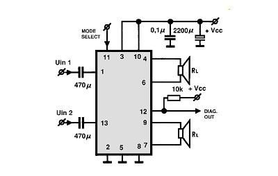
A simple Class B power amplifier can be constructed using the TDA8560 audio integrated circuit (IC). The TDA8560 amplifier features an internally fixed voltage gain, ensuring excellent channel balance. This audio amplifier project is capable of delivering dual 40-watt...
The audio amplifier illustrated in this circuit diagram is a straightforward and efficient audio amplifier circuit based on the TDA1308 integrated class-AB stereo headphone amplifier. This device is manufactured using a 1 mm Complementary Metal Oxide Semiconductor (CMOS) process...
The LM2876 audio power amplifier circuit can be designed as a simple, high-efficiency power audio amplifier capable of delivering 40W of continuous average power to an 8-ohm load with a total harmonic distortion plus noise (THD+N) of 0.1% from...
This circuit illustrates the power supply wiring diagram for the Nissan 300ZX, a sports car known as the Fairlady Z. Components include the lighting switch, ECCS, and fuse. The power supply wiring diagram for the Nissan 300ZX is essential for...