
State Variable Oscillator

The described audio oscillator circuit utilizes a state variable design, which is well-suited for generating low-distortion sine and cosine waveforms. The architecture consists of two integrators, which perform the mathematical integration necessary for generating the sine and cosine outputs. The summer combines the outputs of the integrators to produce the required waveforms, while the feedback loop ensures stability and control over the oscillation characteristics.
The use of the Burr-Brown UAF42 state variable filter is significant due to its integrated precision components, which enhance the performance and reliability of the oscillator. The circuit's design allows for easy adjustments via the variable resistor VR1, which modifies the damping factor to achieve the desired oscillation frequency and amplitude.
The implementation of a closed-loop control system with a PI Controller further enhances the oscillator's performance by continuously adjusting the output to minimize error, thus maintaining consistent waveform characteristics. This approach is particularly advantageous in applications requiring precise signal generation, such as audio synthesis and testing.
In summary, the combination of a state variable oscillator design, precision components, and a control system results in a robust and versatile audio oscillator capable of producing high-quality sine and cosine waveforms across a specified frequency range. The detailed analysis and implementation considerations provide a solid foundation for further development and experimentation in audio oscillator design.The major functional blocks necessary to design a general purpose audio oscillator, and give all the details of my current prototype. Implementation is in the mode of an analog computer, since the desired outputs are sine and cosine values as a function of time.
The following snapshot shows my prototype connected to an X-Y oscilloscope, to display a Lissajous pattern. The circle shown on the scope indicates a nearly perfect 90 degree phase shift between sine and cosine outputs. This quadrature relationship is maintained across the frequency range of the oscillator. I`ve always been fascinated by oscillators, because so many of my past breadboards oscillated but shouldn`t have.
And even when I want a circuit to oscillate, it often seems to be out of control. I have found that a number of authors, including Bob Metzler 1 and Don Lancaster 2, identify the state variable oscillator as the circuit of choice for generating low distortion sine waves for audio use. These authors don`t show the details of how to implement such a circuit, but luckily one day while surfing the web I came across a reference to the article "Design for a Low-Distortion, Fast-Settling Source" in the August 1980 issue of the Hewlett-Packard Journal 3.
That article describes the internal workings of the HP8903A Audio Measurement System, including sketch schematics. Based on this information, I have been able to develop the following analysis. The electronic circuit needed to satisfy this equation is a simple analog computer having two integrators and a summer, as shown in this simulation diagram.
The integrator outputs are identified by the state variables x1 and x2. This circuit is paraphrased from an excellent application note 4 for the Burr-Brown UAF42 state variable filter. Pin numbers shown are for the UAF42, which I used because it contains precision integrator capacitors, and because it is easily available from Digi-Key.
Burr-Brown isn`t the only source for analog function circuits. Analog Devices also has a similar line of parts which is available through distribution. Of course, you can breadboard this with any old opamps and capacitors you happen to have available. Parts values shown in parentheses are internal to the UAF42, and would have to be replaced with discrete components if other opamps are used. Opamps like the TL082 and LF353 have performance characteristics similar to the UAF42. With the parts values shown, the circuit will oscillate at around 160 Hz when you set the damping factor slightly negative with VR1.
Restore damping factor to zero (VR1 near center of range) to maintain steady oscillation. If you use a 10-turn potentiometer for VR1, you should be able to stabilize output amplitude enough to make a quick distortion measurement. Assuming you aren`t at or near clipping, harmonic distortion will be so low as to be unmeasureable. Now that we`ve shown that the basic idea works, let`s take a look at what attributes would be desired for a general purpose audio oscillator.
In the following table I list design goals as well as actual results measured on my prototype, shown above. Spectra were plotted with 10 dB/division on the vertical axis, using an HP3580A. Achieving these goals is not trivial. We often think of a light bulb as the symbol for bright ideas and innovation. In this case however, it will take more than a simple light bulb to achieve the stated goals. Since we are in the mode of analog computation, let`s consider the use of a closed loop control system 5 to maintain stable sine wave oscillation.
To do this I`ve added a Detector and a Proportional/Integral (PI) Controller to the Oscillator. In some texts, these blocks would be called the Sensor, the Compensator, and the Plant, respectively. The only additional block needed is an error detector, shown below as a summer producing an error voltage which is the difference between a reference volt
🔗 External reference
Related Circuits
The tee attenuator offers optimal dynamic linear range attenuation of up to 100 dB, even at a frequency of 10.7 MHz with appropriate layout. The tee attenuator is a crucial component in RF and audio applications where signal integrity and...

This is a 100 MHz Varicap Oscillator circuit. This circuit can provide modulation signals of less than 28 V and a frequency deviation of 28 MHz peak-to-peak. The 100 MHz Varicap Oscillator circuit is designed to generate high-frequency signals suitable...
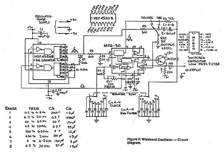
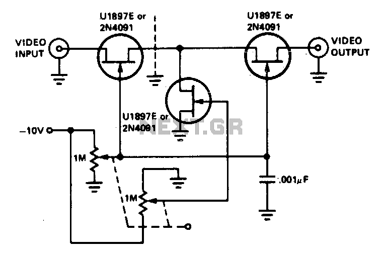
A low distortion audio frequency sine wave can be generated by passing the output of a simple square wave oscillator through a sharp cutoff low-pass filter to attenuate the odd harmonic components. The output level of the sine wave...
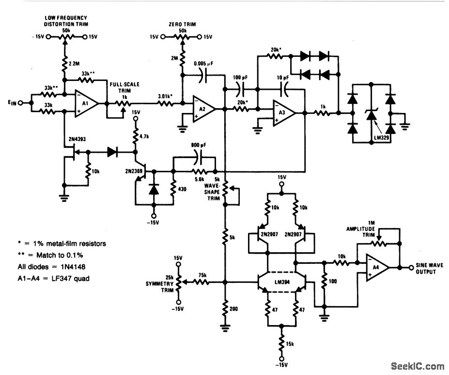
For a 0- to 10-V input, this circuit generates sine-wave outputs ranging from 1 Hz to 20 kHz, achieving linearity better than 0.2%. The distortion level is approximately 0.4%, and both the frequency and amplitude of the sine-wave output...
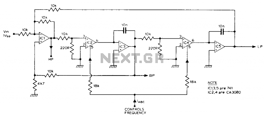
The filter generates three outputs: high-pass, bandpass, and low-pass. The frequency is linearly proportional to the gain of two integrators. Two CA3080 operational amplifiers (IC2, IC4) provide variable gain, with the resonant frequency being proportional to the current. Using...
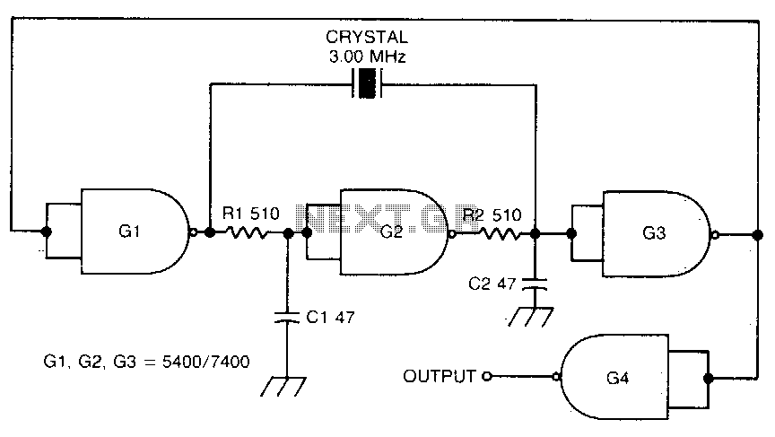
This circuit oscillates without the crystal. When the crystal is included in the circuit, the frequency will match that of the crystal. The circuit exhibits good starting characteristics even with low-quality crystals. This circuit design features a basic oscillator configuration...