
Audio Oscillator
A detailed analysis of the circuit reveals a sophisticated approach to generating a low distortion sine wave suitable for audio applications. The use of a switched capacitor filter allows for dynamic adjustment of the cutoff frequency, making the circuit versatile across a wide frequency range. The integration of a clock signal not only facilitates the desired frequency control but also ensures that the filtering process effectively reduces unwanted harmonics. The sixth-order Butterworth design of the MF6-50 filter is particularly advantageous as it provides a smooth frequency response with minimal ripple, which is critical in audio applications where fidelity is paramount.
The configuration of the clock frequency and the divide-by-56 counter establishes a robust framework for generating both sine and square wave outputs. This dual output capability enhances the circuit's utility, allowing for various testing and signal generation scenarios. The careful design of the secondary R-C filter further mitigates potential interference from clock frequency components, ensuring that the output remains clean and usable for audio frequency testing.
The selection of component values in the R-C networks is crucial; the choice of a 25 kΩ potentiometer over a 40 kΩ variant improves frequency resolution, thereby enhancing the precision of the generated sine wave. This attention to detail in component selection and circuit design underscores the importance of achieving high performance in audio frequency generation applications.
In conclusion, the circuit described is a well-engineered solution for generating low distortion sine waves across a broad frequency range, with built-in mechanisms to minimize harmonic distortion and ensure signal integrity. The integration of a switched capacitor filter with adjustable cutoff frequency and the ability to produce both sine and square wave outputs makes this circuit an excellent choice for various audio applications.A low distortion audio frequency sine wave can be easily generated by passing the output of a simple square wave oscillator through a sharp cut off low pass filter to attenuate the odd harmonic components. The output level of the sine wave is precisely defined by the rail voltage and the gain or loss in the filter.
A problem is that most filters h ave a fixed cut off frequency hence such a sine wave source is restricted to a small frequency range. There is, however, one type of integrated circuit package containing a switched capacitor fitter in which the cut off frequency can be controlled by the frequency of a clock running at a multiple of the cut off frequency.
The circuit described in this article makes use of a switched capacitor low pass filter type MF6-50 (a sixth order Butterworth) which operates with a clock frequency 50 times its cut off frequency. By controlling the frequency of the clock, the cut off frequency can be set to a range of values extending to above 20 kHz.
Using this filter, the circuit forms a variable frequency sine wave oscillator which can be tuned, at constant output level, over a frequency range of 2 Hz to 20 kHz with harmonic components less than 0. 1 percent of the fundamental frequency amplitude, that is, more than 60 dB below that amplitude. As the sine wave is formed from a square wave, the square wave is also available as an alternative output.
The basis of the system is shown in the block diagram, Figure 1. A clock (fck), tunable within the range of 112 Hz to 1. 12 MHz drives both the switched capacitor fitter and a divide by 56 counter which gives square wave output in the range of 2 Hz to 20 kHz. The counter output is fed to the input of the filter which has a cut off` frequency (fc) equal to fck divided by 50, that is, 12 percent higher than the output frequency of the counter.
With this arrangement, odd order harmonics in the square wave are attenuated to a level less than 60 dB below the fundamental frequency. Whatever the fundamental frequency, the cut off frequency tracks at 12 percent higher because both are controlled by the same clock source.
A characteristic of the filter is that it produces components near clock frequency 34 dB down from the fundamental frequency. These can be clearly seen on the CRO display and the spectrum plot of the filter output illustrated in Figure 2.
The actual components are the clock frequency itself plus difference components between the clock frequency and the fundamental frequency. For general audio frequency testing, these components, around 56 times the operating frequency, are possibly unlikely to upset the results of the testing.
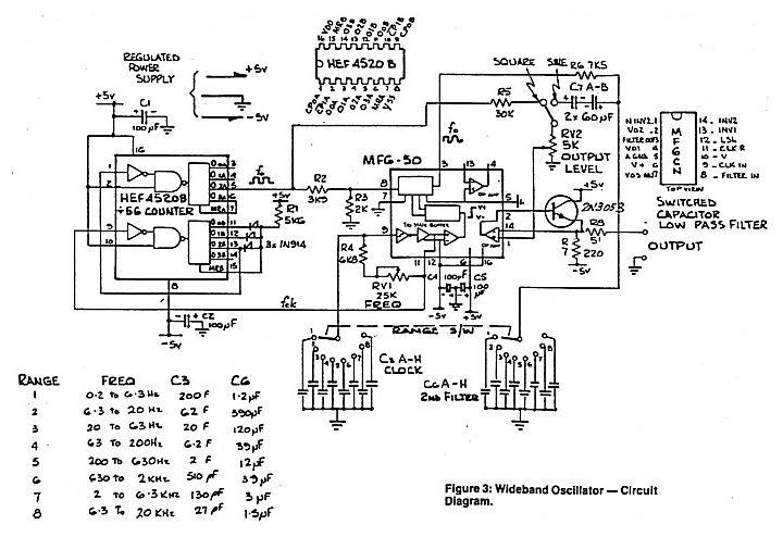
Notwithstanding this, their presence is a little disconcerting hence a simple secondary R-C filter is included, at the output of the switched capacitor filter, to reduce their level. The complete circuit is shown in Figure 3. In addition to the switched capacitor filter, the MF6-50 package includes circuitry which can be connected up to form the clock by the addition of an external resistance-capacitance network which determines the frequency of oscillation.
A frequency range of 112 Hz to 1. 12 MHz can easily be covered with four ranges of selected capacity using a 40 kohm potentiometer, however it was found that eight ranges using a 25 kohm potentiometer was more satisfactory, firstly because of the improved resolution in setting a given frequency and secondly because of a problem in making the secondary R-C filter effective over too wide a range. The clock R-C network in Figure 3 is made up of R4, RV1 and C3A-H. The secondary R-C filter is provided by resistor R6 and capacitors C6A-H switched in tandem with those selected for clock frequency range.
The circuit reduces the high frequency ripple component to 55 dB below the operating frequency level at the high frequency end of the selected range (refer to Figure 4) and 45 dB below at the low frequency end 🔗 External reference
Related Circuits
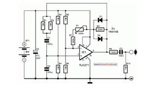
A small audio test generator is very useful for quickly tracing a signal through an audio unit. Its main purpose is speed rather than refinement. An audio test generator is an essential tool in the field of audio engineering, primarily...

This design circuit for audio amplifiers with DC coupling to the load is not commonly used today, despite its clear advantages. One advantage is the elimination of the need for a second (symmetric) power supply, and another is the...
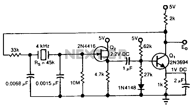
The Pierce circuit oscillates at 4 kHz. At low frequencies, the crystal's internal series resistance Rs is quite high (45 kΩ at 4 kHz). Therefore, an FET-based source follower is included to prevent Q1 from loading the crystal output. The...
The TDA8581 from Philips Semiconductors is a 1-watt Bridge Tied Load (BTL) audio power amplifier capable of delivering 1 watt output power into an 8 ohm load. The TDA8581 is designed for audio amplification applications, particularly in consumer electronics such...
The hum noise is produced by an electronic device with improper design. To address this issue, it is essential to identify the source of the hum. This involves checking the grounding, cabling, casing, and other factors that may contribute...
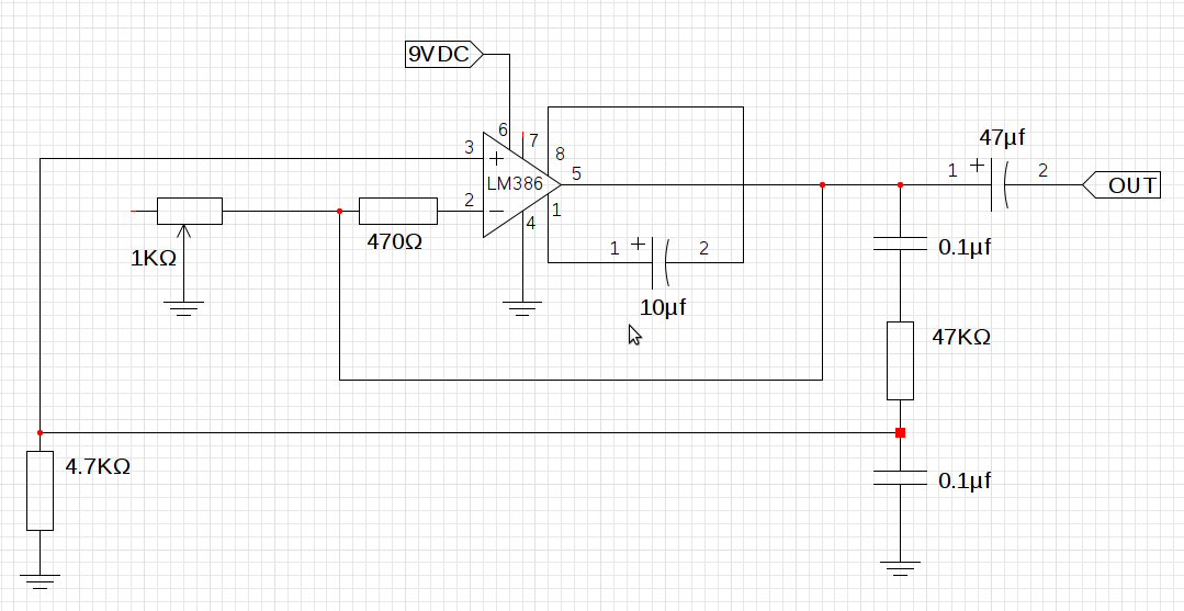
The design utilizes the LM386n-1 integrated circuit, powered by a single power supply to maintain a compact layout. There is a need to control the frequency, and the user is inquiring about which component values should be adjusted for...
Warning: include(partials/cookie-banner.php): Failed to open stream: Permission denied in /var/www/html/nextgr/view-circuit.php on line 713
Warning: include(): Failed opening 'partials/cookie-banner.php' for inclusion (include_path='.:/usr/share/php') in /var/www/html/nextgr/view-circuit.php on line 713