
Audio Mixer with one transistor
This audio mixer circuit employs a single transistor to mix multiple audio signals into one output. The configuration typically involves a bipolar junction transistor (BJT) or a field-effect transistor (FET) that serves as the primary amplifying element. In this design, the base of the transistor is driven by the input audio signals, which can be derived from various sources such as microphones or other audio devices.
The emitter of the transistor is configured to be current-controlled, allowing for precise regulation of the output signal. This current control mechanism helps to maintain a stable output level despite variations in input signal amplitudes. The collector is the output terminal where the mixed audio signal is taken. The design ensures that the majority of the driving current is directed through the collector, optimizing the efficiency of the circuit.
To implement this mixer, appropriate resistor values must be selected to set the biasing conditions for the transistor. The resistors connected to the base determine the input impedance and affect the overall gain of the circuit. Capacitors may also be included in the design to filter out unwanted frequencies and to couple audio signals without affecting the DC biasing of the transistor.
The overall performance of the audio mixer can be enhanced by ensuring proper power supply decoupling and grounding techniques to minimize noise and interference. When designing the circuit, considerations such as the required gain, bandwidth, and load impedance should be taken into account to achieve the desired audio quality.This one transistor audio mixer is used in an amplifier circuit design with base driven transistor and with its emitter being current controlled, most of the driving current flows through the collector away. Using the values in the audio mi.. 🔗 External reference
Related Circuits
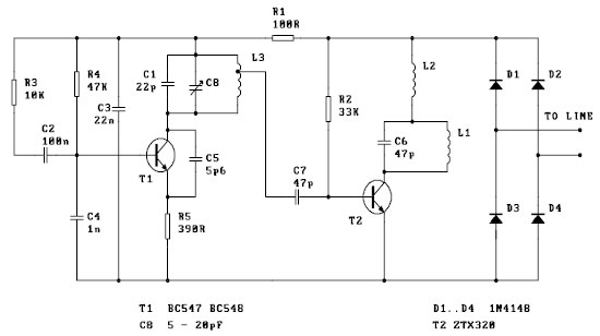
This FM spy telephone circuit is connected in series with the phone line. When there is a signal on the wires, this transmitter will radiate airwaves through the wires, which act as an antenna. There is no need for...
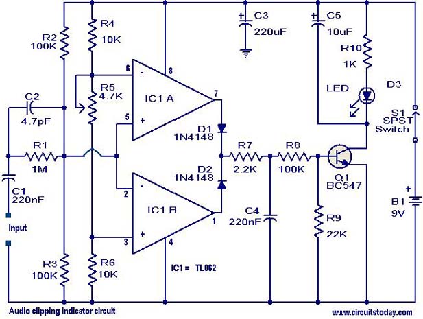
This circuit is designed to detect clipping in a specific waveform. Clipping occurs when the amplitude of a waveform decreases before reaching its expected limit. The circuit activates an LED as an indication that the tested signal is experiencing...
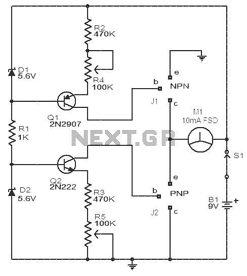
This circuit is a simple device for testing the hfe (current gain) of both PNP and NPN transistors, with the capability to measure hfe values as high as 1000. It operates using two constant current sources formed by transistors...
A lot of friends ask me a circuit AUDIO MIXER, for various uses. I will begin with a circuit which you can it manufacture, as you want. This you can place in the MODULES of inputs any circuit you...
The Metal-Oxide-Semiconductor Field-Effect Transistor (MOSFET) is analogous to the Junction Field-Effect Transistor (JFET) in several aspects. Both types are voltage-driven unipolar devices that rely on either electron or hole movement, but not both, unlike bipolar transistors. A key structural...
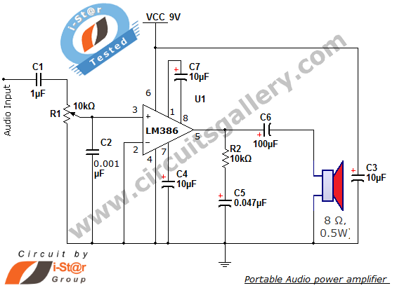
The i-St@r presents a simple mini audio amplifier circuit schematic utilizing the LM386 low voltage audio power amplifier IC. This circuit is designed to power medium-sized speakers from a music player that typically drives only earphones (LM386 headphone). The...