
stepper ttl
The schematic for the stepper motor control circuit includes several key components that work together to ensure proper functionality and control. The three integrated circuits typically used include a microcontroller or a dedicated stepper motor driver IC, which generates the control signals required for the operation of the motor. The PNP transistors serve as switches that are activated by the control signals from the ICs, allowing higher current to flow through the motor coils.
Each PNP transistor is connected to a specific coil of the stepper motor, and the diodes placed in parallel with these transistors protect the circuit from voltage spikes caused by inductive loads. When a coil is turned off, the collapsing magnetic field can induce a high-voltage spike in the opposite direction, which can potentially damage sensitive components. The diodes clamp these spikes, allowing the current to safely recirculate through the coil until it dissipates.
The 7805 voltage regulator is a crucial component that ensures a stable 5V output, which is necessary for the logic levels of the control ICs. This regulator can accept a range of input voltages, providing flexibility in power supply options. The choice of PNP transistors is particularly important in this application, as they are more effective in sinking current, which aligns with the requirements of the TTL logic levels used in the circuit.
The control interface includes a speed potentiometer and a direction switch. The speed potentiometer adjusts the voltage level fed into the control circuitry, thereby regulating the speed of the motor. The direction switch allows the user to change the polarity of the signals sent to the motor, effectively reversing its direction of rotation.
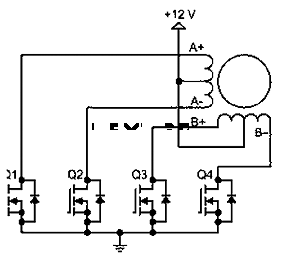
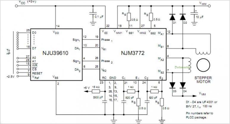
The unique characteristics of stepper motors allow them to maintain their position when powered, which is advantageous in applications requiring precise control. However, it is important to note that while stepper motors can handle continuous current, they can still overheat if driven excessively, so care should be taken to manage their operational limits. To completely stop the motor and allow free rotation, it is necessary to cut the power supply to the motor coils, as this will prevent the coils from maintaining a holding torque.The schematic (below) shows the electronics required to drive a stepper motor. Three commonly available chips and four power transistors are pretty much all that is needed for complete control of a stepper motor. Four PNP power transistors boost the weak electronic signals into current powerful enough to drive the motor coils.
The diodes next to e ach transistor short out the nasty backlash that is generated each time a coil switches off. As a coil`s magnetic field collapses, the reverse induction can generate a momentary hundred volt spike that can fry electronics (I learned that one the hard way ). The reason for using PNP transistors instead of the more common NPN variety is that TTL chips are better at sinking current than sourcing it.
Some types of chips are particularly sensitive to voltage fluctuations. The 7805 power regulator will take any voltage between 6v and 12v DC and turn it into a smooth 5v to power the chips. All the parts needed to build this circuit are available at Radio Shack, but be aware that Radio Shack`s prices for components are literally quadruple that of other electronics stores.
The completed circuit has two controls; the speed potentiometer, and the direction switch. The higher the resistance of the potentiometer, the slower the motor will turn. At low resistance settings the motor will turn at several revolutions per second, but beyond a certain limit the motor will be unable to keep up and will start to skip steps and vibrate. At the other extreme one can easily achieve speeds lower than 1 RPM. Disconnecting the potentiometer (which is equivalent to an infinite resistance) will stop the motor, but leave it powered so that the shaft won`t free-wheel.
Unlike regular motors, stepper motors are designed to handle continuous current in their coils. One cannot burn out a stepper motor. The best way to completely turn off the motor (to let it free-wheel) is to disconnect the motor`s power. 🔗 External reference
Related Circuits
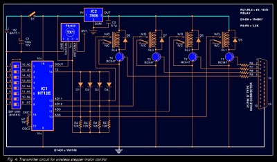
Stepper motors are widely used in applications such as process control, machine tools, and robotics. In particular, remote control of stepper motors is essential in robotics and process control. This document provides the circuit diagrams for both the transmitter...
A bipolar stepper motor drive circuit is presented, utilizing eight transistors to operate two phases. This bipolar drive circuit can accommodate both four-wire and six-wire stepper motors; however, it is primarily designed for four-wire bipolar configurations, which can significantly...
Any stepper motor can be utilized as a generator. Unlike other types of generators, a stepper motor generates a significant induced voltage even at low rotational speeds. A stepper motor operates by converting electrical energy into mechanical motion through a...
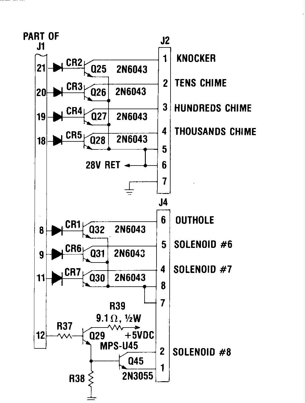
A proposed solution is being tested to prevent overvoltage from reaching the irreplaceable IC U5 - A1752CF after either the switch drives or returns experience a static electric shock or encounter the 24VDC solenoid bus. The protection mechanism is...
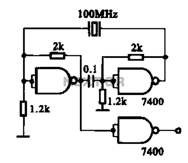
Crystal oscillator integrated circuits, specifically two diagrams of oscillator circuits with oscillation frequencies of 10 MHz and 20 MHz. Crystal oscillators are essential components in various electronic applications, providing stable frequency references for timing and synchronization purposes. The circuits presented...
This device is a two-line audio EMI filter array designed for speaker applications. It provides greater than 35 dB attenuation at frequencies ranging from 800 MHz to 3.0 GHz. Additionally, this device offers ESD protection by clamping transients from...