
Stepper Motor Controllers
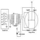
The described circuit serves as a basic stepper motor controller, leveraging standard electronic components to create an economical solution for driving stepper motors. The design typically includes a microcontroller or a simple control logic circuit that outputs control signals to the transistors, which act as switches to energize the motor coils in the correct sequence.
The circuit can incorporate a H-bridge configuration for bidirectional control of the stepper motor, allowing it to rotate in both clockwise and counterclockwise directions. Each transistor in the circuit is responsible for controlling one phase of the motor, enabling precise control over the stepping sequence.
To ensure compatibility with various stepper motors, the circuit should be designed to handle the motor's voltage and current ratings. The use of surplus transistors is advantageous as it reduces costs, but care must be taken to select transistors that can handle the necessary load without overheating.
Additionally, the circuit can be connected to a computer through a USB interface or a serial communication protocol, allowing for easy programming and control via software. This adaptability makes the circuit suitable for various applications, including robotics, CNC machines, and automated systems, where precise movement control is required.
In conclusion, this circuit represents a practical and economical solution for controlling stepper motors, making it accessible for hobbyists and professionals alike. Its simplicity and adaptability to computer control enhance its utility across a range of applications.The circuit is very simple and inexpensive. This is good thing because most commercial stepper motor controller ICs are quite expensive. This circuit is built from standard components and can easily be adapted to be controlled by a computer. If you use cheap surplus transistors and stepper motor, the price of the circuit can be kept to under $10.
🔗 External reference
Related Circuits
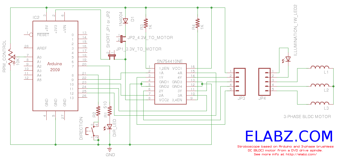
Constructing a stroboscope (zoetrope) using an Arduino and the spindle motor from a damaged Xbox 360 DVD drive. Includes zoetrope animations, Arduino code, and circuit schematic. The project involves utilizing an Arduino microcontroller to control the spindle motor extracted from...

If the control circuit of this motor driver is based on a microcontroller or digital component, it is advisable to implement a buffer for each port that controls the stepper motor driver. This precaution helps prevent overloading the microcontroller...
Stepper motors are a recurring topic of interest. This circuit converts a clock signal from a square wave generator into signals that have a 90-degree phase difference, which are necessary for driving the stepper motor windings. The trade-off for...
S1 and S2 are normally open, push-to-close, momentary switches. The diodes can be either red or green and are used solely for indicating direction. The TIP31 transistors may need to be adjusted based on the motor specifications. It is...
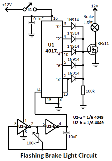
This flashing brake light circuit is designed for motorcycles. When the brake light switch S1 is closed, power is supplied to U1 and U2. The circuit utilizes two inverters from U2. The flashing brake light circuit operates by utilizing a...
The simplest method to drive a stepper motor with a lower current rating is by utilizing the ULN2003. The ULN2003 consists of seven Darlington transistors and can handle up to 500mA per channel, with an internal voltage drop of...