
Stepper Motor Generator
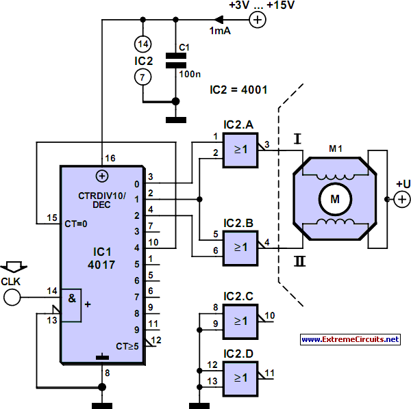
The described circuit effectively utilizes a 4017 decade counter to generate the necessary control signals for a stepper motor. The 4017 counter divides the input clock frequency by ten, which is critical for creating the required phased signals for the motor operation. The phase difference is achieved through the use of inverting OR gates, allowing for the generation of two square waves that are 90 degrees apart.
The sequence of energizing the motor windings is crucial for proper stepper motor operation. Each state of the 4017 counter corresponds to a specific configuration of the motor windings, ensuring that the motor steps through its sequence in a controlled manner. The arrangement of the windings—alternating between positive and negative states—ensures that the rotor moves in a precise, incremental manner.
To drive the stepper motor effectively, a driver circuit is essential due to the limited current output from the OR gate. This driver circuit typically consists of transistors or MOSFETs that can handle higher current loads, allowing for the stepper motor to be powered efficiently. The driver receives the low-current control signals from the OR gates and amplifies them to a suitable level for the motor operation.
In summary, this circuit design demonstrates an efficient method for controlling stepper motors by converting clock signals into phased outputs, utilizing a decade counter, and incorporating a driver stage to manage the power requirements of the motor. Careful consideration of the timing and sequencing of the outputs is necessary to ensure smooth operation of the stepper motor, making this circuit a practical solution for applications requiring precise motor control.Stepper motors are a subject that keeps recurring. This little circuit changes a clock signal (from a square wave generator) into signals with a 90-degree phase difference, which are required to drive the stepper motor windings. The price we pay for the simplicity is that the frequency is reduced by a factor of four. This isn`t really a problem, s ince we just have to increase the input frequency to compensate. The timing diagram clearly shows that the counter outputs of the 4017 are combined using inverting OR gates to produce two square waves with a phase difference. This creates the correct sequence for powering the windings: the first winding is negative and the second positive, both windings are negative, the first winding is positive and the second negative, and finally both windings are positive.
Internally, the 4017 has a divide-by-10 counter followed by a decoder. Output 0` is active (logic one) as long as the internal counter is at zero. At the next positive edge of the clock signal the counter increments to 1 and output 1` becomes active. This continues until output 4` becomes a logic one. This signal is connected to the reset input, which immediately resets the counter to the zero` state.
If you were to use an oscilloscope to look at this output, you would have to set it up very precisely before you would be able to see this pulse; that`s how short it is. The output of an OR gate can only supply several mA, which is obviously much too little to drive a stepper motor directly.
A suitable driver circuit, which goes between the generator and stepper motor. 🔗 External reference
Related Circuits
A footstepping effort-based locomotion interface is described. Built around an inexpensive and readily available exercise machine, it provides an effective interface for walking through virtual environments. The footstepping effort-based locomotion interface utilizes a low-cost exercise machine, such as a treadmill or...
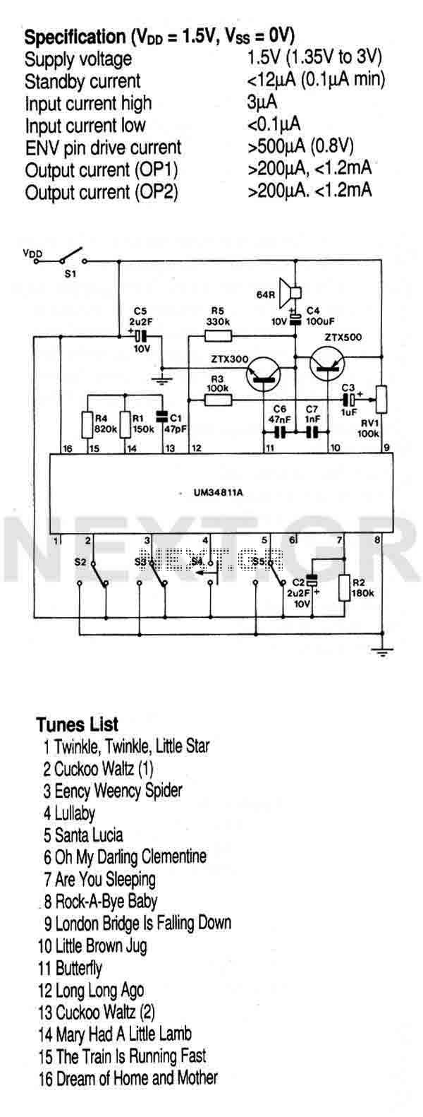
This circuit utilizes a preprogrammed multi-instrument melody generator integrated circuit (IC), which features a 512-note memory capable of producing 16 distinct tunes. The extensive control options allow for the playback of all tunes in a loop or stopping at...
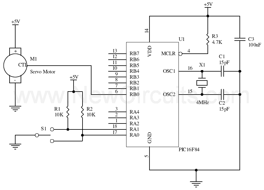
This simple microcontroller circuit regulates a servo motor based on a 3-state switch. The servo motor functions as an actuator with three positions. It consists of three wires: one for VCC, one for ground, and a third for position...
This is a design circuit for a simple function generator. Built around a single 8038 waveform generator IC, this circuit produces sine, square, or triangle waves from 20Hz to 200kHz in four switched ranges. There are both high and...
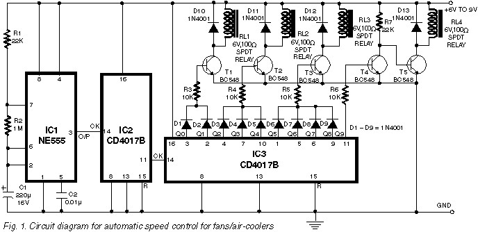
During summer nights, the temperature is initially quite high. As time passes, the temperature starts dropping. Also, after a person falls asleep, the metabolic rate of one's body decreases. Thus, initially the fan/cooler needs to be run at full...
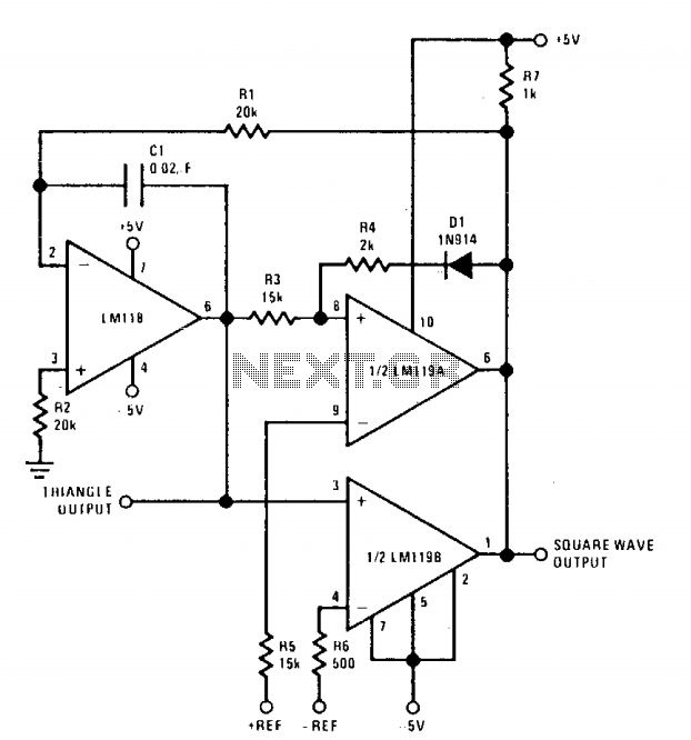
The positive and negative peak amplitudes can be controlled with an accuracy of approximately ±0.01 V through a DC input. Additionally, the output frequency and symmetry are easily adjustable. The oscillator is composed of an integrator and two comparators;...